Physics A Level
Chapter 7: Matter and materials 7.4 Compressive and tensile forces
Physics A Level
Chapter 7: Matter and materials 7.4 Compressive and tensile forces
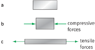
A pair of forces is needed to change the shape of a spring. If the spring is being squashed and shortened, we say that the forces are compressive. More usually, we are concerned with stretching a spring, in which case the forces are described as tensile (Figure 7.5).
When a wire is bent, some parts become longer and are in tension while other parts become shorter and are in compression. Figure 7.6 shows that the line AA becomes longer when the wire is bent and the line BB becomes shorter. The thicker the wire, the greater the compression and tension forces along its edges.
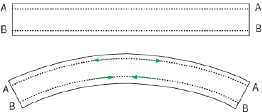
outside of the bend) and compressive forces on the inside of the bend
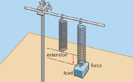
It is simple to investigate how the length of a helical spring is affected by the applied force or load. The spring hangs freely with the top end clamped firmly (Figure 7.7). A load is added and gradually increased.
For each value of the load, the extension of the spring is measured. Note that it is important to determine the increase in length of the spring, which we call the extension.
We can plot a graph of force against extension to find the stiffness of the spring, as shown in Figure 7.8.
|
|
Hooke’s law
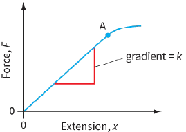
The usual way of plotting the results would be to have the force along the horizontal axis and the extension along the vertical axis. This is because we are changing the force (the independent variable) and this results in a change in the extension (the dependent variable). The graph shown in Figure 7.7 has extension on the horizontal axis and force on the vertical axis. This is a departure from the convention because the gradient of the straight section of this graph turns out to be an important quantity, known as the spring constant.
For a typical spring, the first section of this graph OA is a straight line passing through the origin. The extension x is directly proportional to the applied force (load) F. The behaviour of the spring in the linear region OA of the graph can be expressed by the following equation:
$x\, \propto \,F\,or\,F\, = \,kx$
where k is the spring constant (sometimes called the stiffness or force constant of the spring). The spring constant is the force per unit extension, given by:
$k = \frac{F}{x}$
The SI unit for the force constant is newtons per metre or $N\,{m^{ - 1}}$. We can find the force constant k from the gradient of section OA of the graph:
$k = gradient$
stiffer spring will have a larger value for the force constant k. Beyond point A, the graph is no longer a straight line; its gradient changes and we can no longer use the equation $F = kx$.
If a spring or anything else responds to a pair of tensile forces in the way shown in section OA of Figure 7.7, we say that it obeys Hooke’s law. A material obeys Hooke’s law if the extension produced in it is proportional to the applied force (load).
The point A is known as the limit of proportionality. This is the point beyond which the extension is no longer proportional to the force.
If you apply a small force to a spring and then release it, it will return to its original length (this is elastic deformation.). However, if you apply a large force, the spring may not return to its original length; the spring has become permanently deformed (this is plastic deformation.). The force beyond which the spring becomes permanently deformed is known as the elastic limit.
The elastic limit is not necessarily the same point as the limit of proportionality, although they are likely to be close to each other.
This use of the word ‘elastic’ in elastic limit is slightly different from the idea of an elastic collision covered in Chapter 6. But the two ideas are related.
Question
11) Figure 7.9 shows the force–extension graph for a wire that is stretched and then released.
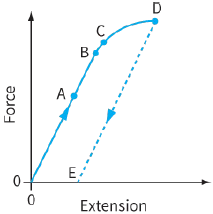
a: Which point shows the limit of proportionality?
b: Which point shows the elastic limit?
12) Figure 7.11 shows the force–extension graphs for four springs, A, B, C and D.
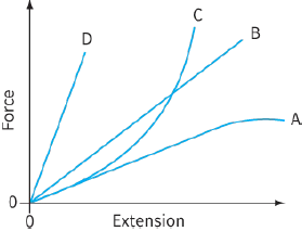
a: State which spring has the greatest value of force constant.
b: State which is the least stiff.
c: State which of the four springs does not obey Hooke’s law.
PRACTICAL ACTIVITY 7.1
Investigating springs
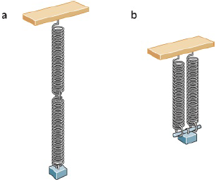
Springs can be combined in different ways (Figure 7.10): end-to-end (in series) and side-by-side (in parallel). Using identical springs, you can measure the force constant of a single spring, and of springs in series and in parallel. Before you do this, predict the outcome of such an experiment. If the force constant of a single spring is k, what will be the equivalent force constant of:
- two springs in series?
- two springs in parallel?
This approach can be applied to combinations of three or more springs.