Physics A Level
Chapter 9: Kirchhoff’s laws 9.4 Resistor combinations
Physics A Level
Chapter 9: Kirchhoff’s laws 9.4 Resistor combinations
You are already familiar with the formulae used to calculate the combined resistance R of two or more resistors connected in series or in parallel. To derive these formulae we have to use Kirchhoff’s laws.
Resistors in series
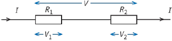
Take two resistors of resistances R1 and R2 connected in series (Figure 9.16). According to Kirchhoff’s first law, the current in each resistor is the same. The p.d. V across the combination is equal to the sum of the p.d.s across the two resistors:
$V = {V_1} + {V_2}$
Since $V = IR\,,\,{V_1} = I{R_1}$ and ${V_2} = I{R_2}$, we can write:
$IR = I{R_1} + I{R_2}$
Cancelling the common factor of current I gives:
$R = {R_1} + {R_2}$
Questions
10) Calculate the combined resistance of two $5\Omega $ resistors and a $10\Omega $ resistor connected in series.
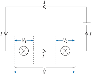
11) The cell shown in Figure 9.17 provides an e.m.f. of $2.0 V$. The p.d. across one lamp is $1.2 V$. Determine the p.d. across the other lamp.
12) You have five $1.5 V$ cells. How would you connect all five of them to give an e.m.f. of:
a: $7.5 V$
b: $1.5 V$
c: $4.5 V$?
Resistors in parallel
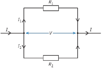
For two resistors of resistances R1 and R2 connected in parallel (Figure 9.18), we have a situation where the current divides between them. Hence, using Kirchhoff’s first law, we can write:
$I = {I_1} + {I_2}$
If we apply Kirchhoff’s second law to the loop that contains the two resistors, we have:
${I_1}{R_1} - {I_2}{R_2} = 0\,V$
(because there is no source of e.m.f. in the loop).
This equation states that the two resistors have the same p.d. V across them. Hence we can write:
$\begin{array}{l}
I = \frac{V}{R}\\
{I_1} = \frac{V}{{{R_1}}}\\
{I_2} = \frac{V}{{{R_2}}}
\end{array}$
Substituting in $I = {I_1} + {I_2}$ and cancelling the common factor V gives:
$\frac{1}{R} = \frac{1}{{{R_1}}} + \frac{1}{{{R_2}}}$
For three or more resistors, the equation for total resistance R becomes:
$\frac{1}{R} = \frac{1}{{{R_1}}} + \frac{1}{{{R_2}}} + \frac{1}{{{R_3}}} + ...$
To summarise, when components are connected in parallel:
- all have the same p.d. across their ends
- the current is shared between them
- we use the reciprocal formula to calculate their combined resistance.
Questions
13) Calculate the total resistance of four $10\Omega $ resistors connected in parallel.
14) Calculate the resistances of the following combinations:
a: $100\Omega $ and $200\Omega $ in series
b: $100\Omega $ and $200\Omega $ in parallel
c: $100\Omega $ and $200\Omega $ in series and this in parallel with $200\Omega $.
15) Calculate the current drawn from a $12 V$ battery of negligible internal resistance connected to the ends of the following:
a: $500\Omega $ resistor
b: $500\Omega $ and $1000\Omega $ resistors in series
c: $500\Omega $ and $1000\Omega $ resistors in parallel.
16) You are given one $200\Omega $ resistor and two $100\Omega $ resistors. What total resistances can you obtain by connecting some, none, or all of these resistors in various combinations?
Solving problems with parallel circuits
Here are some useful ideas that may help when you are solving problems with parallel circuits (or checking your answers to see whether they seem reasonable).
- When two or more resistors are connected in parallel, their combined resistance is smaller than any of their individual resistances. For example, three resistors of $2\Omega \,,\,3\Omega $ and $6\Omega $ connected together in parallel have a combined resistance of $1\Omega $. This is less than the smallest of the individual resistances.
This comes about because, by connecting the resistors in parallel, you are providing extra pathways for the current. Since the combined resistance is lower than the individual resistances, it follows that connecting two or more resistors in parallel will increase the current drawn from a supply. Figure 9.19 shows a hazard that can arise when electrical appliances are connected in parallel.
- When components are connected in parallel, they all have the same p.d. across them. This means that you can often ignore parts of the circuit that are not relevant to your calculation.
- Similarly, for resistors in parallel, you may be able to calculate the current in each one individually, then add them up to find the total current. This may be easier than working out their combined resistance using the reciprocal formula. (This is illustrated in Question 19.)
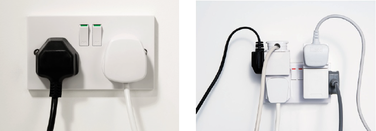
connected in parallel. This reduces the total resistance and increases the current drawn, to the point
where it becomes dangerous
Questions
17) Three resistors of resistances $20\Omega \,,\,30\Omega $ and $\,60\Omega $ are connected together in parallel. Select which of the following gives their combined resistance:
$110\Omega \,,\,50\Omega \,,\,20\Omega \,,\,10\Omega $
(No need to do the calculation!)
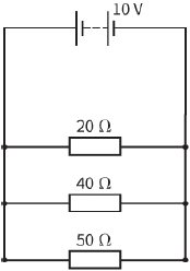
18) In the circuit in Figure 9.20 the battery of e.m.f. $10 V$ has negligible internal resistance. Calculate the current in the $\,20\Omega $ resistor shown in the circuit.
19) Determine the current drawn from the battery in Figure 9.20.
20) What value of resistor must be connected in parallel with a $\,20\Omega $ resistor so that their combined resistance is $\,10\Omega $?
21) You are supplied with a number of $\,100\Omega $ resistors. Describe how you could combine the minimum number of these to make a $\,250\Omega $ resistor.
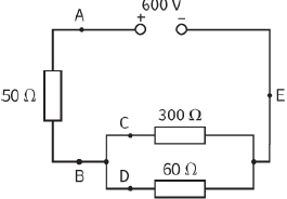
22) Calculate the current at each point (A–E) in the circuit shown in Figure 9.21.
PRACTICAL ACTIVITY 10.1
Ammeters and voltmeters
Ammeters and voltmeters are connected differently in circuits (Figure 9.22). Ammeters are always connected in series, since they measure the current in a circuit. For this reason, an ammeter should have as low a resistance as possible so that as little energy as possible is dissipated in the ammeter itself. Inserting an ammeter with a higher resistance could significantly reduce the current flowing in the circuit. The ideal resistance of an ammeter is zero. Digital ammeters have very low resistances.
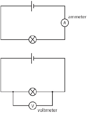
Voltmeters measure the potential difference between two points in the circuit. For this reason, they are connected in parallel (i.e., between the two points), and they should have a very high resistance to take as little current as possible. The ideal resistance of a voltmeter would be infinite. In practice, voltmeters have typical resistance of about $1M\Omega $. A voltmeter with a resistance of $10M\Omega $ measuring a p.d. of $2.5 V$ will take a current of $2.5 \times {10^{ - 7}}$ A and dissipate just $0.625\mu J$ of heat energy from the
circuit every second.
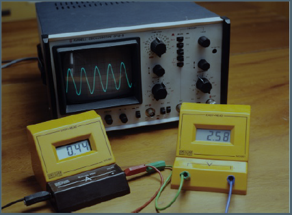
Figure 9.23 shows some measuring instruments.
Question
23) a: A $10 V$ power supply of negligible internal resistance is connected to a $100\,\Omega $ resistor. Calculate the current in the resistor.
b: An ammeter is now connected in the circuit, to measure the current. The resistance of the ammeter is $5.0\,\Omega $. Calculate the ammeter reading.
EXAM-STYLE QUESTIONS
1) Which row in this table is correct? [1]
| A | Kirchhoff’s first law is an expression of the conservation of charge. | Kirchhoff’s second law is an expression of the conservation of charge. |
| B | Kirchhoff’s first law is an expression of the conservation of charge. | Kirchhoff’s second law is an expression of the conservation of energy. |
| C | Kirchhoff’s first law is an expression of the conservation of energy. | Kirchhoff’s second law is an expression of the conservation of charge. |
| D | Kirchhoff’s first law is an expression of the conservation of energy. | Kirchhoff’s second law is an expression of the conservation of energy. |
2) What is the current I1 in this circuit diagram? [1]
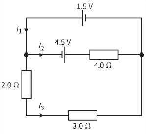
A: $ - 0.45 A$
B: $+0.45 A$
C: $+1.2 A$
D: $+1.8 A$
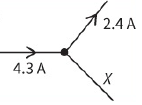
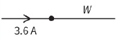
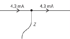
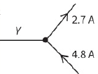
3) Use Kirchhoff’s first law to calculate the unknown currents in these examples.
|
|
|
|
For each example, state the direction of the current. [4]
4) This diagram shows a part of a circuit.
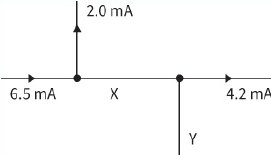
Copy the circuit and write in the currents at X and at Y, and show their directions. [2]
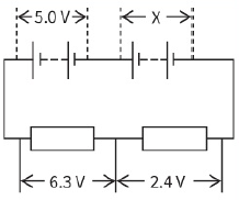
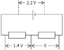
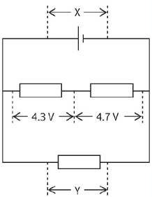
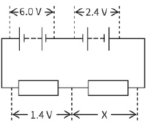
5) Look at these four circuits.
|
|
|
|
Determine the unknown potential difference (or differences) in each case. [5]
6) A filament lamp and a $220\,\Omega $ resistor are connected in series to a battery of e.m.f. $6.0 V$. The battery has negligible internal resistance. A high-resistance voltmeter placed across the resistor measures $1.8 V$.
Calculate:
a: the current drawn from the battery [1]
b: the p.d. across the lamp [1]
c: the total resistance of the circuit [1]
d: the number of electrons passing through the battery in a time of 1.0 minute. [4]
(The elementary charge is $1.6 \times {10^{ - 19}}C$.)
[Total: 7]
7) The circuit diagram shows a $12 V$ power supply connected to some resistors.
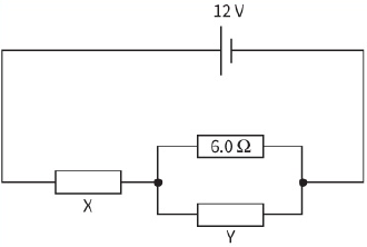
The current in the resistor X is $2.0 A$ and the current in the $6.0\,\Omega $ resistor is $0.5 A$. Calculate:
a: the current in resistor Y [1]
b: the resistance of resistor Y [2]
c: the resistance of resistor X. [2]
[Total: 5]
8) a: Explain the difference between the terms e.m.f. and potential difference. [2]
b: This circuit contains batteries and resistors. You may assume that the batteries have negligible internal resistance.
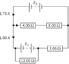
i- Use Kirchhoff’s first law to find the current in the $8.00\,\Omega $ and $8.00\,\Omega $ resistors. [1]
ii- Calculate the e.m.f. of ${E_1}$. [2]
iii- Calculate the value of ${E_2}$. [2]
iv- Calculate the current in the $12.00\,\Omega $ resistor. [2]
[Total: 9]
9) a: Explain why an ammeter is designed to have a low resistance. [1]
A student builds the circuit, as shown, using a battery of negligible internal resistance. The reading on the voltmeter is $9.0 V$.
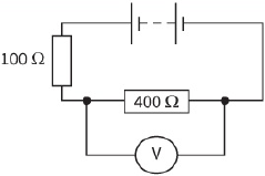
b: i- The voltmeter has a resistance of $12.00\,\Omega $. Calculate the e.m.f. of the battery. [4]
ii- The student now repeats the experiment using a voltmeter of resistance $12\,k\Omega $. Show that the reading on this voltmeter would be $9.5 V$. [3]
iii- Refer to your answers to i and ii and explain why a voltmeter should have as high a resistance as possible. [2]
[Total: 10]
10) a: Explain what is meant by the resistance of a resistor. [1]
b: This diagram shows a network of resistors connected to a cell of e.m.f. $6.0 V$.
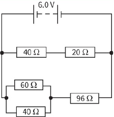
Show that the resistance of the network of resistors is $40\,\Omega $. [3]
c: Calculate the current in the $60\,\Omega $ resistor. [3]
[Total: 7]
SELF-EVALUATION CHECKLIST
After studying the chapter, complete a table like this:
| I can | See topic… | Needs more work | Almost there | Ready to move on |
| state and use Kirchhoff’s first law | 9.1, 9.3 | |||
| state and use Kirchhoff’s second law that states that the sum of the e.m.f.s around any loop in a circuit is equal to the sum of the p.d.s around the loop | 9.2, 9.3 | |||
| calculate the total resistance of two or more resistors in series | 9.4 | |||
| calculate the resistance of two or more resistors in parallel | 9.4 | |||
| understand that ammeters have a low resistance and are connected in series in a circuit | 9.4 | |||
| understand that voltmeters have a high resistance and are connected in parallel in a circuit. | 9.4 |