Physics A Level
Chapter 11: Practical circuits 11.1 Internal resistance
Physics A Level
Chapter 11: Practical circuits 11.1 Internal resistance
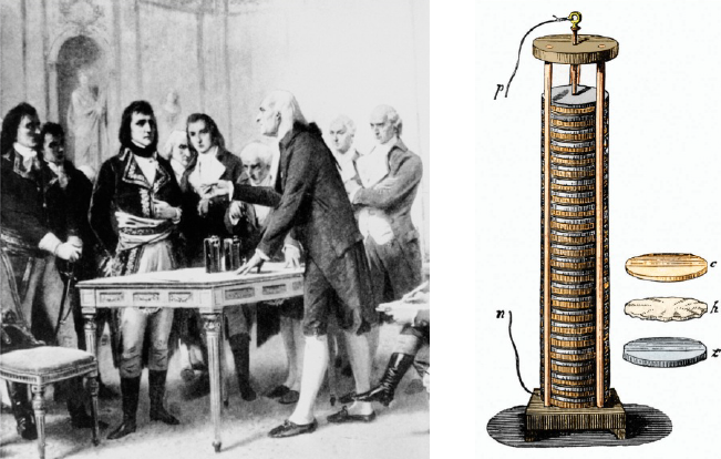
You will have learnt that, when you use a power supply or other source of e.m.f., you cannot assume that it is providing you with the exact voltage across its terminals as suggested by the value of its e.m.f. There are several reasons for this. For example, the supply may not be made to a high degree of precision, or the batteries may have become flat, and so on. However, there is a more important factor, which is that all sources of e.m.f. have an internal resistance. For a power supply, this may be due to the wires and components inside, whereas for a cell the internal resistance is due to the chemicals within it.
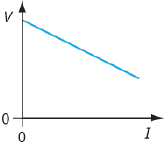
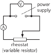
Experiments show that the voltage across the terminals of the power supply depends on the circuit of which it is part. In particular, the voltage across the power supply terminals decreases if it is required to supply more current.
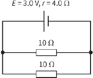
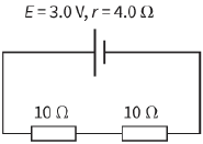
Figure 11.2 shows a circuit you can use to investigate this effect, and a sketch graph showing how the voltage across the terminals of a power supply might decrease as the supplied current increases.
|
|
The charges moving round a circuit have to pass through the external components and through the internal resistance of the power supply. These charges gain electrical energy from the power supply. This energy is lost as thermal energy as the charges pass through the external components and through the internal resistance of the power supply. Power supplies and batteries get warm when they are being used.
(Try using a cell to light a small torch bulb; feel the cell before connecting to the bulb, and then feel it again after the bulb has been lit for about 15 seconds.)
The reason for this heating effect is that some of the electrical potential energy of the charges is transformed to internal energy as they do work against the internal resistance of the cell.
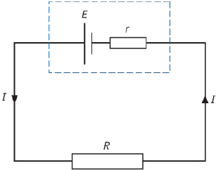
It can often help to solve problems if we show the internal resistance r of a source of e.m.f. explicitly in circuit diagrams (Figure 11.3). Here, we are representing a cell as if it were a ‘perfect’ cell of e.m.f. E, together with a separate resistor of resistance r. The dashed line enclosing E and r represents the fact that these two are, in fact, a single component.
diagram
Now we can determine the current when this cell is connected to an external resistor of resistance R. You can see that R and r are in series with each other. The current I is the same for both of these resistors. The combined resistance of the circuit is thus $R + r$, and we can write:
$E = I(R + r)$ or $E = IR + Ir$
We cannot measure the e.m.f. E of the cell directly, because we can only connect a voltmeter across its terminals. This terminal p.d. V across the cell is always the same as the p.d. across the external resistor.
Therefore, we have:
$V = IR$
This will be less than the e.m.f. E by an amount Ir. The quantity Ir is the potential difference across the internal resistor. If we combine these two equations, we get:
$V = E − Ir$
where E is the emf of the source, I is the current in the source and r is the internal resistance of the source.
or
terminal $p.d. = e.m.f. − p.d$ across the internal resistance
The potential difference across the internal resistance indicates the energy transferred to the internal resistance of the supply. If you short-circuit a battery with a piece of wire, a large current will flow, and the battery will get warm as energy is transferred within it. This is also why you may damage a power supply by trying to make it supply a larger current than it is designed to give.
Questions
1) A battery of e.m.f. $5.0 V$ and internal resistance $2.0\,\Omega $ is connected to an $8.0\,\Omega $ resistor. Draw a circuit diagram and calculate the current in the circuit.
2) a: Calculate the current in each circuit in Figure 11.4.
b: Calculate also the potential difference across the internal resistance for each cell, and the terminal
p.d.
|
|
3) Four identical cells, each of e.m.f. $1.5 V$ and internal resistance $0.10\,\Omega $, are connected in series. A lamp of resistance $2.0\,\Omega $ is connected across the four cells. Calculate the current in the lamp.
PRACTICAL ACTIVITY 12.1
Determining e.m.f. and internal resistance
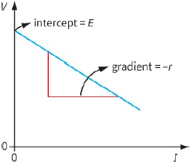
You can get a good idea of the e.m.f. of an isolated power supply or a battery by connecting a digital voltmeter across it. A digital voltmeter has a very high resistance ($ \sim {10^7}\,\Omega $), so only a tiny current will pass through it. The potential difference across the internal resistance will then only be a tiny fraction of the e.m.f. If you want to determine the internal resistance r as well as the e.m.f. E, you need to use a circuit like that shown in Figure 11.2. When the variable resistor is altered, the current in the circuit changes and measurements can be recorded of the circuit current I and terminal p.d. V. The internal resistance r can be found from a graph of V against I (Figure 11.5).
Compare the equation $V = E − Ir$ with the equation of a straight line $y = mx + c$. By plotting V on the yaxis and I on the x-axis, a straight line should result. The intercept on the y-axis is E, and the gradient is $−r$.
Questions
4) When a high-resistance voltmeter is placed across an isolated battery, its reading is $3.0 V$. When a $10\,\Omega $ resistor is connected across the terminals of the battery, the voltmeter reading drops to $2.8 V$. Use this information to determine the internal resistance of the battery.
5) The results of an experiment to determine the e.m.f. E and internal resistance r of a power supply are shown in Table 11.1. Plot a suitable graph and use it to find E and r.
| V / V | 1.43 | 1.33 | 1.18 | 1.10 | 0.98 |
| I / A | 0.10 | 0.30 | 0.60 | 0.75 | 1.00 |
The effects of internal resistance
You cannot ignore the effects of internal resistance. Consider a battery of e.m.f. $3.0 V$ and of internal resistance $1.0\,\Omega $. The maximum current that can be drawn from this battery is when its terminals are shorted-out. (The external resistance $R \approx 0$.) The maximum current is given by:
$\begin{array}{l}
\max imum\,current = \frac{E}{r}\\
= \frac{{3.0}}{{1.0}}\\
= 3.0A
\end{array}$
The terminal p.d. of the battery depends on the resistance of the external resistor. For an external resistor of resistance $1.0\,\Omega $, the terminal p.d. is $1.5 V$ – half of the e.m.f. The terminal p.d. approaches the value of the e.m.f. when the external resistance R is very much greater than the internal resistance of the battery. For example, a resistor of resistance $1000\,\Omega $ connected to the battery gives a terminal p.d. of $2.997 V$. This is almost equal to the e.m.f. of the battery. The more current a battery supplies, the more its terminal p.d. will decrease. An example of this can be seen when a driver tries to start a car with the headlamps on. The starter motor requires a large current from the battery, the battery’s terminal p.d.
drops and the headlamps dim.
Question
6) A car battery has an e.m.f. of $12 V$ and an internal resistance of $0.04\,\Omega $. The starter motor draws a current of $100 A$.
a: Calculate the terminal p.d. of the battery when the starter motor is in operation.
b: Each headlamp is rated as ‘$12 V, 36 W$’. Calculate the resistance of a headlamp.
c: To what value will the power output of each headlamp decrease when the starter motor is in operation? (Assume that the resistance of the headlamp remains constant.)