Physics A Level
Chapter 11: Practical circuits 11.3 Sensors
Physics A Level
Chapter 11: Practical circuits 11.3 Sensors
Light-dependent resistors as sensors
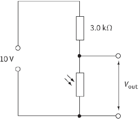
How is a light-dependent resistor (LDR) used as a sensor or transducer? A voltage is needed to drive the output device, such as a voltmeter, yet the LDR only produces a change in resistance. The sensor must use this change in resistance to generate the change in voltage. The solution is to place the LDR in series with a fixed resistor, as shown in Figure 11.8.
The voltage of the supply is shared between the two resistors in proportion to their resistance so, as the light level changes and the LDR’s resistance changes, so does the voltage across each of the resistors.
The two resistors form a potential divider whose output changes automatically with changing light intensities.
Questions
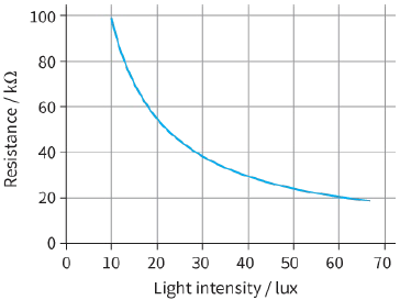
8) What is the voltage across the $3.0k\Omega $ resistor in Figure 11.9 when the light intensity is 10 lux?
9) The circuit shown in Figure 11.8 produces a decreasing output voltage when the light intensity increases. How can the circuit be altered to produce an increasing output voltage as the light intensity increases?
Thermistors as a sensors
The thermistors that we refer to in this course are known as negative temperature coefficient (NTC) thermistors. This means that, when the temperature rises, the resistance of the thermistor falls. This happens because the thermistor is made from a semiconductor material. One property of a semiconductor is that when the temperature rises the number of free electrons increases, and thus the resistance falls.
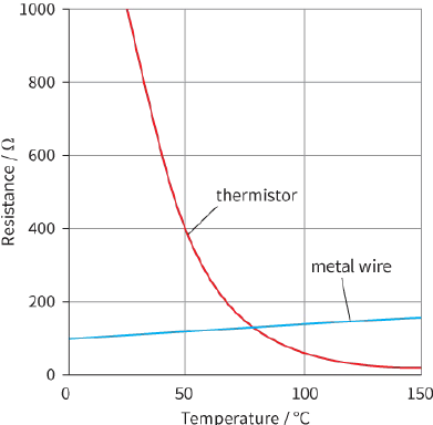
Figure 11.10 shows a graph of the resistance of a thermistor and the resistance of a metal wire plotted against temperature. You can see that the resistance of a metal wire increases with increase in temperature. A metal wire is not a negative temperature device, but it could be used as a sensing device.
A thermistor is more useful than a metal wire because there is a much larger change in resistance with change in temperature. However, the change in resistance of a thermistor is not linear with temperature; indeed, it is likely to be an exponential decrease. This means that any device used to measure temperature electronically must be calibrated to take into account the resistance–temperature graph. The scale on an ordinary laboratory thermometer between ${0^ \circ }C$ and ${100^ \circ }C$ is divided up into 100 equal parts, each of which represents ${1^ \circ }C$. If the resistance of a thermistor were divided like this, the scale would be incorrect.
The thermistor can be used as a sensing device in the same way as an LDR. Instead of sensing a change in light level, it senses a change in temperature.
Questions
10) Explain how a thermistor can be used as a transducer.
11) State two similarities between an LDR and a thermistor.
12) Design a circuit using the thermistor in Figure 11.10 that uses a cell of $10 V$ and produces an output voltage of $5 V$ at ${50^ \circ }C$. Explain whether the voltage output of your circuit increases or decreases as the temperature rises.