Physics A Level | Chapter 11: Practical circuits 11.4 Potentiometer circuits
A potentiometer is a device used for comparing potential differences. For example, it can be used to measure the e.m.f. of a cell, provided you already have a source whose e.m.f. is known accurately. As we will see, a potentiometer can be thought of as a type of potential divider circuit.
A potentiometer consists of a piece of resistance wire, usually $1 m$ in length, stretched horizontally between two points. In Figure 11.11, the ends of the wire are labelled A and B. A driver cell is connected across the length of wire. Suppose this cell has an e.m.f. ${E_o}$ of $2.0 V$. We can then say that point A is at a voltage of $2.0 V$, B is at $0 V$, and the midpoint of the wire is at $1.0 V$. In other words, the voltage decreases steadily along the length of the wire.
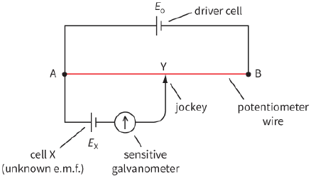
Now, suppose we wish to measure the e.m.f. ${E_X}$ of cell X (this must have a value less than that of thedriver cell). The positive terminal of cell X is connected to point A. (Note that both cells have theirpositive terminals connected to A.) A lead from the negative terminal is connected to a sensitive galvanometer (such as a microammeter), and a lead from the other terminal of the galvanometer ends with a metal jockey. This is a simple connecting device with a very sharp edge that allows very precise positioning on the wire.
If the jockey is touched onto the wire close to point A, the galvanometer needle will deflect in one direction. If the jockey is touched close to B, the galvanometer needle will deflect in the opposite direction. Clearly, there must be some point Y along the wire that, when touched by the jockey, gives zero deflection – the needle moves neither to the left nor the right.
In finding this position, the jockey must be touched gently and briefly onto the wire; the deflection of the galvanometer shows whether the jockey is too far to the left or right. It is important not to slide the jockey along the potentiometer wire as this may scrape its surface, making it non-uniform so that the voltage does not vary uniformly along its length.
When the jockey is positioned at Y, the galvanometer gives zero deflection, showing that there is no current through it. This can only happen if the potential difference across the length of wire AY is equal to the e.m.f. of cell X. We can say that the potentiometer is balanced. If the balance point was exactly halfway along the wire, we would be able to say that the e.m.f. of X was half that of the driver cell. This technique – finding a point where there is a reading of zero – is known as a null method.
To calculate the unknown e.m.f. ${E_X}$ we measure the length AY. Then we have:
${E_X} = \frac{{AY}}{{AB}} \times {E_o}$
where ${E_o}$ is the e.m.f. of the driver cell.
The potentiometer can be thought of as a potential divider because the point of contact Y divides the resistance wire into two parts, equivalent to the two resistors of a potential divider.
Comparing e.m.f.s with a potentiometer
When a potentiometer is balanced, no current flows from the cell being investigated. This means that its terminal p.d. is equal to its e.m.f.; we do not have to worry about the potential difference across the internal resistance. This is a great advantage that a potentiometer has over a voltmeter, which must draw a small current in order to work.
However, there is a problem: the driver cell is supplying current to the potentiometer, and so the p.d.
between A and B will be less than the e.m.f. of the driver cell (some volts are lost because of its internal resistance). To overcome this problem, we use the potentiometer to compare p.d.s. Suppose we have two cells whose e.m.f.s ${E_X}$ and ${E_Y}$ we want to compare. Each is connected in turn to the potentiometer, giving balance points at C and D–see Figure 11.12. (In the diagram, you can see immediately that ${E_Y}$ must be greater than ${E_X}$ because D is further to the right than C.)
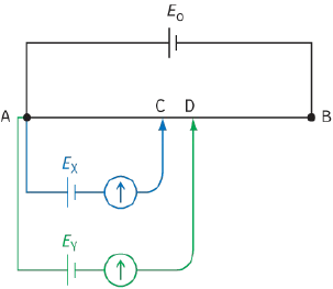
The ratio of the e.m.f.s of the two cells will be equal to the ratio of the two lengths AC and AD:
$\frac{{{E_X}}}{{{E_Y}}} = \frac{{AC}}{{AD}}$
If one of the cells used has an accurately known e.m.f., the other can be calculated with the same degree of accuracy.
Comparing p.d.s
The same technique can be used to compare potential differences. For example, two resistors could be connected in series with a cell (Figure 11.13). The p.d. across one resistor is first connected to the potentiometer and the balance length found. This is repeated with the other resistor and the new balance point is found. The ratio of the lengths is the ratio of the p.d.s.
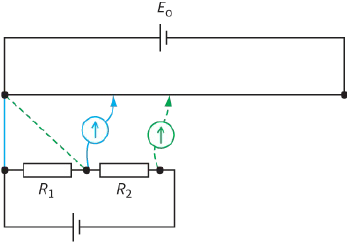
Since both resistors have the same current flowing through them, the ratio of the p.d.s is also the ratio of their resistances.
Question
13) To make a potentiometer, a driver cell of e.m.f. $4.0 V$ is connected across a $1.00 m$ length of resistance wire.
a: What is the potential difference across each $1 cm$ length of the wire? What length of wire has a p.d. of $1.0 V$ across it?
b: A cell of unknown e.m.f. E is connected to the potentiometer and the balance point is found at a distance of $37.0 cm$ from the end of the wire to which the galvanometer is connected. Estimate the value of E. Explain why this can only be an estimate.
c: A standard cell of e.m.f. $1.230 V$ gives a balance length $31.2 cm$. Use this value to obtain a more accurate value for E.
EXAM-STYLE QUESTIONS
1) A resistor of resistance $6.0\Omega $ and a second resistor of resistance $3.0\Omega $ are connected in parallel across a battery of e.m.f. $4.5 V$ and internal resistance $0.50\Omega $.
What is the current in the battery? [1]
A: $0.47 A$
B: $1.8 A$
C: $3.0 A$
D: $11 A$
2) This diagram shows a potential divider.
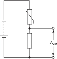
What happens when the temperature decreases? [1]
A: The resistance of the thermistor decreases and ${V_{out}}$ decreases.
B: The resistance of the thermistor decreases and ${V_{out}}$ increases.
C: The resistance of the thermistor increases and ${V_{out}}$ decreases.
D: The resistance of the thermistor increases and ${V_{out}}$ increases.
3) A single cell of e.m.f. $1.5 V$ is connected across a $0.30\Omega $ resistor. The current in the circuit is $2.5 A$.
a: Calculate the terminal p.d. and explain why it is not equal to the e.m.f. of the cell. [2]
b: Show that the internal resistance r of the cell is $0.30\Omega $. [3]
c: It is suggested that the power dissipated in the external resistor is a maximum when its resistance R is equal to the internal resistance r of the cell.
i- Calculate the power dissipated when $R = r$. [1]
ii- Show that the power dissipated when $R = 0.50\Omega $ and $R = 0.20\Omega $ is less than that dissipated when $R = r$, as the statement suggests. [4]
[Total: 10]
4) A student is asked to compare the e.m.f.s of a standard cell and a test cell. He sets up the circuit shown using the test cell.
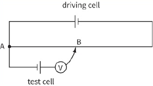
a: i- Explain why he is unable to find a balance point and state the change he must make in order to achieve balance. [2]
ii- State how he would recognise the balance point. [1]
b: He achieves balance when the distance AB is $22.5 cm$. He repeats the experiment with a standard cell of e.m.f. of $1.434 V$. The balance point using this cell is at $34.6 cm$. Calculate the e.m.f. of the test cell. [2]
[Total: 5]
5) a: Explain what is meant by the internal resistance of a cell. [2]
b: When a cell is connected in series with a resistor of $2.00\Omega $ there is a current of $0.625 A$. If a second resistor of $2.00\Omega $ is put in series with the first, the current falls to $0.341 A$.
Calculate:
i- the internal resistance of the cell [2]
ii- the e.m.f. of the cell. [1]
c: A car battery needs to supply a current of $200 A$ to turn over the starter motor. Explain why a battery made of a series of cells of the type described b would not be suitable for a car battery. [2]
[Total: 7]
6) a: State what is meant by the term e.m.f. of a cell. [2]
A student connects a high-resistance voltmeter across the terminals of a battery and observes a reading of $8.94 V$. He then connects a $12\Omega $ resistor across the terminals and finds that the potential difference falls to $8.40 V$.
b: Explain why the measured voltage falls. [2]
c: i- Calculate the current in the circuit. [2]
ii- Calculate the internal resistance of the cell. [2]
iii- State any assumptions you made in your calculations. [1]
[Total: 9]
7) This diagram shows two circuits that could be used to act as a dimmer switch for a lamp.
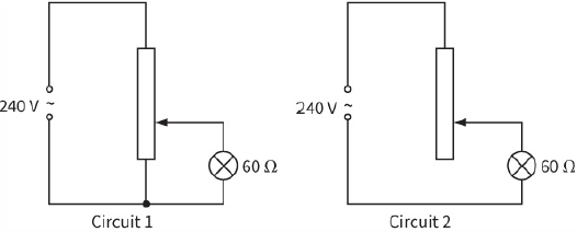
a: Explain one advantage circuit 1 has over circuit 2. [2]
b: i- The lamp is rated at $60 W$ at $240 V$. Calculate the resistance of the lamp filament at its normal operating temperature. [2]
ii- State and explain how the resistance of the filament at room temperature would compare with the value calculated in i. [2]
[Total: 6]
8) This circuit shows a potential divider. The battery has negligible internal resistance and the voltmeter has infinite resistance.
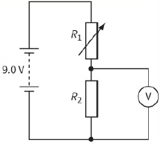
a: State and explain how the reading on the voltmeter will change when the resistance of the variable resistor is increased. [2]
b: Resistor R2 has a resistance of $470\Omega $. Calculate the value of the variable resistor when the reading on the voltmeter is $2.0 V$. [2]
c: The voltmeter is now replaced with one of resistance $2k\Omega $. Calculate the reading on this voltmeter. [2]
[Total: 6]
9) This is a potentiometer circuit.
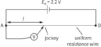
a: i- Sketch a graph of reading on the voltmeter against length, l, as the jockey is moved from point A to point B. [2]
ii- State the readings on the voltmeter when the jockey is connected to A and when it is connected to B. (You may assume that the driver cell has negligible internal resistance.) [1]
iii- Draw a circuit diagram to show how the potentiometer could be used to compare the e.m.f.s of two batteries. [3]
b: When a pair of $4\Omega $ resistors are connected in series with a battery, there is a current of $0.60 A$ current through the battery. When the same two resistors are connected in parallel and then connected across the battery, there is a current of $1.50 A$ through it. Calculate the e.m.f. and the internal resistance of the battery. [4]
[Total: 10]
10) A potentiometer, which consists of a driving cell connected to a resistance wire of length $100 cm$, is used to compare the resistances of two resistors.
a: Draw a diagram to show the circuits that are used to compare the two resistances. [2]
b: When resistor R1 alone is tested the length of resistance wire for balance is $15.4 cm$. There is an uncertainty in measuring the beginning of the resistance wire of $0.1 cm$, and in establishing the balance point of a further $0.1 cm$.
i- Determine the uncertainty in the balance length. [1]
When ${R_1}$ and ${R_2}$ are tested in series the balance length is $42.6 cm$.
There are similar uncertainties in measuring this balance length.
ii- Calculate the ratio of . [1]
iii- Calculate the value of the ration of . [2]
iv- Calculate the uncertainty in the value of the ratio $\frac{{{R_1}}}{{{R_2}}}$. [2]
[Total: 8]
SELF-EVALUATION CHECKLIST
After studying the chapter, complete a table like this:
| I can | See topic… | Needs more work | Almost there | Ready to move on |
| understand the concept of internal resistance of a source of e.m.f. | 11.1 | |||
| solve problems involving internal resistance and e.m.f. and the potential difference across the internal resistance. | 11.1 | |||
|
recognise a potential divider and solve problems using the equation: ${V_{out}} = \left( {\frac{{{R_2}}}{{{R_1} + {R_2}}}} \right) \times {V_{in}}$ |
11.2, 11.3 | |||
| use a potentiometer to compare potential differences. | 11.4 |