Physics A Level
Chapter 13: Superposition of waves 13.3 Interference
Physics A Level
Chapter 13: Superposition of waves 13.3 Interference
Adding waves of different wavelengths and amplitudes results in complex waves – by complex, we really mean not sinusoidal. We can find some interesting effects if we consider what happens when two waves of the same type, and having the same wavelength, overlap at a point. Again, we will use the principle of superposition to explain what we observe.
PRACTICAL ACTIVITY 13.2
Observing interference
Interference of sound waves
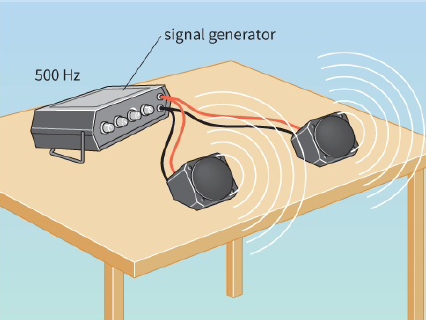
A simple experiment shows what happens when two sets of sound waves meet. Two loudspeakers are connected to a single signal generator (Figure 13.11). They each produce sound waves of the same wavelength. Walk around in the space in front of the loudspeakers; you will hear the resultant effect.
You may predict that we would hear a sound twice as loud as that from a single loudspeaker. However, this is not the case. At some points, the sound is louder than for a single loudspeaker. At other points, the sound is much quieter. The space around the two loudspeakers consists of a series of loud and quiet regions. We are observing the phenomenon known as interference. This phenomenon results in the formation of points of cancellation and reinforcement where two coherent waves pass through each other.
Interference in a ripple tank
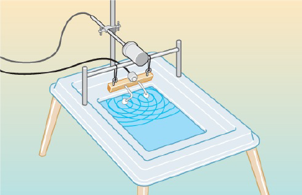
Look at Figure 13.12. The two dippers in the ripple tank should be positioned so that they are just touching the surface of the water. When the bar vibrates, each dipper acts as a point-source of circular ripples spreading outwards. Where these sets of ripples overlap, we observe an interference pattern.
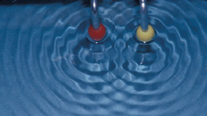
Another way to observe interference in a ripple tank is to use plane waves passing through two gaps in a barrier. The water waves are diffracted at the two gaps and then interfere beyond the gaps. Figure 13.13 shows the interference pattern produced by two vibrating dippers in a ripple tank.
Explaining interference
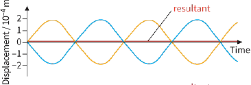
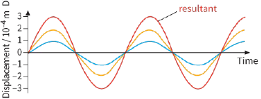
Figure 13.14 shows how interference arises. The loudspeakers in Figure 13.11 (Practical Activity 13.2) are emitting waves that are in phase because both are connected to the same signal generator. At each point in front of the loudspeakers, waves are arriving from the two loudspeakers. At some points, the two waves arrive in phase (in step) with one another and with equal amplitude (Figure 13.14a). The principle of superposition predicts that the resultant wave has twice the amplitude of a single wave. We hear a louder sound.
At other points, something different happens. The two waves arrive completely out of phase or in antiphase (phase difference is ${180^ \circ }$) with one another (Figure 13.14b). There is a cancelling out, and the resultant wave has zero amplitude. At this point, we would expect silence. At other points again, the waves are neither perfectly out of step nor perfectly in step, and the resultant wave has an amplitude less than that at the loudest point.
Where two waves arrive at a point in phase with one another so that they add up, we call this effect constructive interference. Where they cancel out, the effect is known as destructive interference.
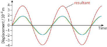
Where two waves have different amplitudes but are in phase (Figure 13.14c), constructive interference results in a wave whose amplitude is the sum of the two individual amplitudes.
|
|
|
|
Question
3) Explain why the two loudspeakers producing sounds of slightly different frequencies will not produce stable effects of interference.
How can we explain the interference pattern observed in a ripple tank (Practical Activity 13.2)? Look at Figure 13.15 and compare it to Figure 13.13. Figure 13.15 shows two sets of waves setting out from their sources. At a position such as A, ripples from the two sources arrive in phase with one another, and constructive interference occurs. At B, the two sets of ripples arrive in antiphase, and there is destructive interference. Although waves are arriving at B, the surface of the water remains approximately flat.
Whether the waves combine constructively or destructively at a point depends on the path difference of the waves from the two coherent sources. The path difference is defined as the extra distance travelled by one of the waves compared with the other.
At point A in Figure 13.15, the waves from the red source have travelled three whole wavelengths. The waves from the yellow source have travelled four whole wavelengths. The path difference between the two sets of waves is one wavelength. A path difference of one wavelength is equivalent to a phase difference of zero. This means that the two waves are in phase, so they interfere constructively.
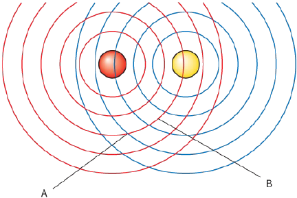
Now think about destructive interference. At point B, the waves from the red source have travelled three wavelengths; the waves from the yellow source have travelled 2.5 wavelengths. The path difference between the two sets of waves is 0.5 wavelengths, which is equivalent to a phase difference of ${180^ \circ }$. The waves interfere destructively because they are in antiphase. The conditions for constructive interference and destructive interference, in general, are outlined next. These conditions apply to all waves (water waves, light, microwaves, radio waves, sound and so on) that show interference effects. In the equations, n is an integer (any whole number, including zero).
For constructive interference the path difference is a whole number of wavelengths:
$path\,difference = 0,\lambda ,2\lambda ,3\lambda ,$ and so on
or
$path\,difference = n\lambda $
For destructive interference the path difference is an odd number of half wavelengths:
$path\,difference = \frac{1}{2}\lambda ,1\frac{1}{2}\lambda ,2\frac{1}{2}\lambda ,$ and so on
or
$path\,difference = (n + \frac{1}{2})\lambda $
PRACTICAL ACTIVITY 13.3
Interference of radiation
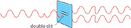
Interference of light
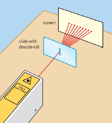
Here is one way to show the interference effects produced by light. A simple arrangement involves directing the light from a laser at a double-slit (Figure 13.16). The slits are two clear lines on a black slide, separated by a fraction of a millimetre. Where the light falls on the screen, a series of equally spaced dots of light are seen (see Figure 13.21). These bright dots are referred to as interference maxima or ‘fringes’, and they are regions where light waves from the two slits are arriving in phase with each other; in other words, there is constructive interference. The dark regions in between are the result of destructive interference.
If you carry out experiments using a laser, you should follow correct safety procedures. In particular, you should wear eye protection and avoid allowing the beam to enter your eye directly.
These bright and dark fringes are the equivalent of the loud and quiet regions that you detected if you investigated the interference pattern of sounds from the two loudspeakers described in Practical Activity 13.2. Bright fringes correspond to loud sound, and dark fringes to quiet sound or silence.
You can check that light is indeed reaching the screen from both slits as follows. Mark a point on the screen where there is a dark fringe. Now carefully cover up one of the slits so that light from the laser is only passing through one slit. You should find that the pattern of interference fringes disappears.
Instead, a broad band of light appears across the screen. This broad band of light is the diffraction pattern produced by a single slit. The point that was dark is now light. Cover up the other slit instead, and you will see the same effect. You have now shown that light is arriving at the screen from both slits, but at some points (the dark fringes) the two beams of light cancel each other out.
You can achieve similar results with a bright light bulb rather than a laser, but a laser is much more convenient because the light is concentrated into a narrow, more intense beam. This famous experiment is called the Young double-slit experiment (discussed in more detail later in this chapter), although Thomas Young had no laser available to him when he first demonstrated it in 1801.
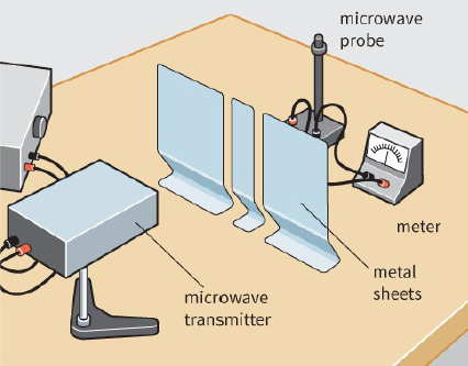
Interference of microwaves
Using $2.8 cm$ wavelength microwave equipment (Figure 13.17), you can observe an interference pattern. The microwave transmitter is directed towards the double gap in a metal barrier. The microwaves are diffracted at the two gaps so that they spread out into the region beyond, where they can be detected using the microwave probe (receiver). By moving the probe around, it is possible to detect regions of high intensity (constructive interference) and low intensity (destructive interference).
The probe may be connected to a meter, or to an audio amplifier and loudspeaker to give an audible output.
Question
4) Look at the experimental arrangement shown in Figure 13.17. Suppose that the microwave probe is placed at a point of low intensity in the interference pattern.
Suggest what will happen if one of the gaps in the barrier is now blocked.
Coherence
We are surrounded by many types of wave – light, infrared radiation, radio waves, sound and so on. There are waves coming at us from all directions. So why do we not observe interference patterns all the time?
Why do we need special equipment in a laboratory to observe these effects?
In fact, we can see interference of light occurring in everyday life. For example, you may have noticed haloes of light around street lamps or the Moon on a foggy night. You may have noticed light and dark bands of light if you look through fabric at a bright source of light. These are all examples of interference effects.
We usually need specially arranged conditions to produce interference effects that we can measure. Think about the demonstration with two loudspeakers. If they were connected to different signal generators with slightly different frequencies, the sound waves might start off in phase with one another, but they would soon go out of phase (Figure 13.18). We would hear loud, then soft, then loud again. The interference pattern would keep shifting around the room – there would be no stable interference pattern of loud and quiet regions.
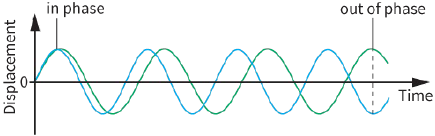
phase with one another
By connecting the two loudspeakers to the same signal generator, we can be sure that the sound waves that they produce are constantly in phase with one another. We say that they act as two coherent sources of sound waves (coherent means sticking together). The sound waves from the loudspeakers has coherence. Coherent sources emit waves that have a constant phase difference. Note that the two waves can only have a constant phase difference if their frequency is the same and remains constant.
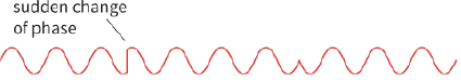
Now think about the laser experiment. Could we have used two lasers producing exactly the same frequency and hence wavelength of light? Figure 13.19a represents the light from a laser. We can think of it as being made up of many separate bursts of light. We cannot guarantee that these bursts from two lasers will always be in phase with one another.
This problem is overcome by using a single laser and dividing its light using the two slits (Figure 13.19b).
The slits act as two coherent sources of light. They are constantly in phase with one another (or there is a constant phase difference between them).
If they were not coherent sources, the interference pattern would be constantly changing, far too fast for our eyes to detect. We would simply see a uniform band of light, without any definite bright and dark regions. From this you should be able to see that, in order to observe interference, we need two coherent sources of waves.
|
|
Question
5) Draw sketches of displacement against time to illustrate the following:
a: two waves having the same amplitude and in phase with one another
b: two waves having the same amplitude and with a phase difference of ${90^ \circ }$
c: two waves initially in phase but with slightly different wavelengths.