Physics A Level
Chapter 13: Superposition of waves 13.5 Diffraction gratings
Physics A Level
Chapter 13: Superposition of waves 13.5 Diffraction gratings
A transmission diffraction grating is similar to the slide used in the double-slit experiment, but with many more slits than just two. It consists of a large number of equally spaced lines ruled on a glass or plastic slide. Each line is capable of diffracting the incident light. There may be as many as 10000 lines per centimetre. When light is shone through this grating, a pattern of interference fringes is seen.
A reflection diffraction grating consists of lines made on a reflecting surface so that light is both reflected and diffracted by the grating. The shiny surface of a CD (compact disc), or a DVD (digital versatile disc), is an everyday example of a reflection diffraction grating. Hold a CD in your hand so that you are looking at the reflection of light from a lamp. You will observe coloured bands (Figure 13.24). A CD has thousands of equally spaced lines of microscopic pits on its surface; these carry the digital information. It is the diffraction from these lines that produces the coloured bands of light from the surface of the CD.

surface, producing a display of spectral colours
Observing diffraction with a transmission grating
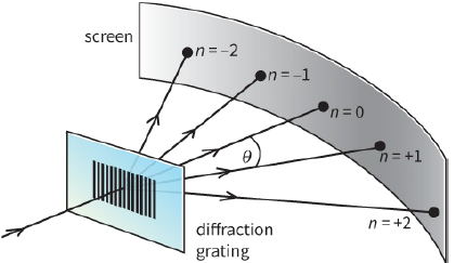
In Figure 13.25, monochromatic light from a laser is incident normally on a transmission diffraction grating. In the space beyond, interference fringes are formed. These can be observed on a screen, as with the double slit. However, it is usual to measure the angle $\theta $ at which they are formed, rather than measuring their separation. With double slits, the fringes are equally spaced and the angles are very small. With a diffraction grating, the angles are much greater and the fringes are not equally spaced.
The bright fringes are also referred to as maxima. The central fringe is called the zeroth-order maximum, the next fringe is the first-order maximum, and so on. The pattern is symmetrical, so there are two firstorder maxima, two second-order maxima, and so on.
maxima on a screen
Explaining the experiment
The principle is the same as for the double-slit experiment, but here we have light passing through many slits. As it passes through each slit, it diffracts into the space beyond. So now we have many overlapping beams of light, and these interfere with one another.
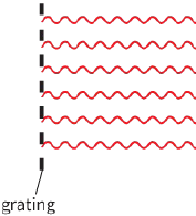
There is a bright fringe, the zeroth-order maximum, in the straight-through direction ($\theta = 0$). This is because all of the rays here are travelling parallel to one another and in phase, so the interference is constructive (Figure 13.26a).
Imagine if you could look through the diffraction grating at the source of light. Your eye would be focused on the light source, which is far away. All the rays with $\theta = 0$ come together at the back of your eye, where an image is formed. It is here that interference occurs.
|
|
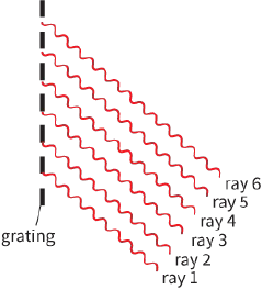
The first-order maximum forms in a specific direction as follows. Diffraction occurs at all of the slits. Rays of light emerge from all of the slits to form a bright fringe – all the rays must be in phase. In the direction of the first-order maximum, ray 1 has travelled the smallest distance (Figure 13.26b). Ray 2 has travelled an extra distance equal to one whole wavelength and is therefore in phase with ray 1. The path difference between ray 1 and ray 2 is equal to one wavelength $\lambda $. Ray 3 has travelled two extra wavelengths and is in phase with rays 1 and 2. In fact, the rays from all of the slits are in step in this direction, and a bright fringe results.
Question
11) Explain how the second-order maximum arises in terms of path difference.
Determining wavelength $\lambda $ with a diffraction grating
By measuring the angles at which the maxima occur, we can determine the wavelength $\lambda $ of the incident monochromatic light. The wavelength $\lambda $ is related to the angle $\theta $ by the equation:
$d\,\sin \theta = n\lambda $
where d is the separation between adjacent lines of the grating, $\theta $ is the angle for the nth-order maximum and $\lambda $ is the wavelength of the monochromatic light incident normally at the diffraction grating. n is known as the order of the maximum; n can only have integer values $0, 1, 2, 3$ and so on. The distance d is also known as the grating element or grating spacing.
Worked example 2 shows how you can determine $\lambda $.
Questions
12) a: For the case described in Worked example 2, with $\lambda = 580\,nm$, calculate the angle $\theta $ for the second-order maximum.
b: Repeat the calculation of $\theta $ for $n = 3, 4$, and so on. Determine how many maxima can be seen.
Explain your answer.
13) Consider the equation. State and explain how the interference pattern would change when:
a: the wavelength of the incident light is increased for the same grating
b: the grating is changed for one with more lines per cm for the same incident light.
14) A student is trying to make an accurate measurement of the wavelength of green light from a mercury lamp. The wavelength $\lambda $ of this light is $546 nm$. Using a double-slit of separation $0.50 mm$, the student can see 10 clear bright fringes on a screen at a distance of $0.80 m$ from the slits. The student can measure their overall width to within $ \pm 1\,mm$ using a ruler.
The student then tries an alternative experiment using a diffraction grating with $3000\,lines\,c{m^{ - 1}}$. The angle between the two second-order maxima can be measured to within $ \pm {0.1^ \circ }$.
a: Determine the width of the 10 fringes that the student can measure in the first experiment.
b: Determine the angle of the second-order maximum that the student can measure in the second experiment.
c: Based on your answers to parts a and b, suggest which experiment you think will give the more accurate value of $\lambda $.
Diffracting white light
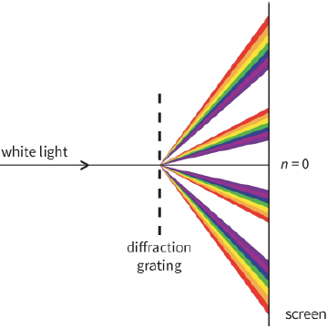
A diffraction grating can be used to split white light up into its component colours. This splitting of light is known as dispersion, shown in Figure 13.27. A beam of white light is shone onto the grating. A zerothorder, white maximum is observed at $\theta = {0^ \circ }$, because all waves of each colour are in phase in this direction.
On either side, a series of spectra appear, with violet closest to the centre and red furthest away. We can see why different wavelengths have their maxima at different angles if we rearrange the equation $d\,\sin \theta = n\lambda $ to give:
$\sin \theta = \frac{{n\lambda }}{d}$
From this it follows that the greater the wavelength $\lambda $, the greater the value of sin $\theta $ and hence the greater the angle $\theta $. Red light is at the long wavelength end of the visible spectrum, and so it appears at the greatest angle.
wavelengths
PRACTICAL ACTIVITY 13.5
Diffraction gratings versus double-slit
It is worth comparing the use of a diffraction grating to determine wavelength with the Young two-slit experiment.
- With a diffraction grating, the maxima are very sharp.
- With a diffraction grating, the maxima are also very bright. This is because rather than contributions from only two slits, there are contributions from a thousand or more slits.
- With double-slit, there may be a large uncertainty in the measurement of the slit separation a. The fringes are close together, so their separation may also be measured imprecisely.
- With a diffraction grating the maxima are widely separated, the angle $\theta $ can be measured to a high degree of precision. So, an experiment with a diffraction grating can be expected to give a value for the wavelength to a much higher degree of precision than a simple double-slit arrangement.
Question
15) White light is incident normally on a diffraction grating with a slit-separation d of $2.00 \times {10^{ - 6}}\,m$. The visible spectrum has wavelengths between $400 nm$ and $700 nm$.
a: Calculate the angle between the red and violet ends of the first-order spectrum.
b: Explain why the second- and third-order spectra overlap.
EXAM-STYLE QUESTIONS
1) Rays of light from two coherent sources produces constructive interference.
Which of the following cannot be the phase difference between these two rays? [1]
A: ${0^ \circ }$
B: ${270^ \circ }$
C: ${360^ \circ }$
D: ${720^ \circ }$
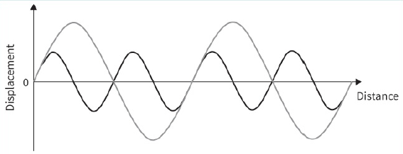
2) a: Copy the waves shown in the diagram onto a sheet of graph paper and use the principle of superposition to sketch the resultant wave. [2]
b: Compare the wavelength of the resultant wave with that of the component waves. [1]
[Total: 3]
3) State how the diffracted pattern will change when:
a: the wavelength of the incident wave is increased [1]
b: the wavelength of the incident wave is decreased. [1]
[Total: 2]
4) Explain why, in remote mountainous regions, such as the Hindu Kush, radio signals from terrestrial transmitters can be received, but television reception can only be received from satellite transmissions. [2]
5) A constant frequency signal from a signal generator is fed to two loudspeakers placed $1.5 m$ apart. A student, who is $8.0 m$ away from the loudspeakers, walks across in a line parallel to the line between the loudspeakers. The student measures the distance between successive spots of loudness to be $1.2 m$.
Calculate:
a: the wavelength of the sound [2]
b: the frequency of the sound (assume the speed of sound is $330\,m\,{s^{ - 1}}$) [2]
[Total: 4]
6) Two signal generators feed signals with slightly different frequencies to two separate loudspeakers. Suggest why a sound of continuously rising and falling loudness is heard. [3]
7) One of the spectral lines from a hydrogen discharge lamp has wavelength $656\,n{m^{ - 1}}$. This light is incident normally at a diffraction grating with $5000\,lines\,c{m^{ - 1}}$.
Calculate the angles for the first- and second-order maxima for this light. [5]
8) a: Explain what is meant by the term superposition. [2]
b: In a double-slit experiment, yellow light of wavelength $590 nm$ from a sodium discharge tube is used. A student sets up a screen $1.8 m$ from the double-slit. The distance between 12 bright fringes is measured to be $16.8mm$.
Calculate the separation of the slits. [3]
c: Describe the effect of:
i- using slits of narrower width, but with the same separation [2]
ii- using slits with a smaller separation, but of the same width. [2]
[Total: 9]
9) a: A laser light is described as producing light that is both highly coherent and highly monochromatic.
Explain what is meant by the terms coherent and monochromatic. [2]
b: This diagram shows the experimental setup (left) used to analyse the spectrum of a sodium discharge lamp with a diffraction grating with $500\,lines\,m{m^{ - 1}}$, and the spectral lines observed (right) in the developed photographic film.
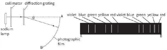
i- Explain why two spectra are observed. [2]
ii- Describe two differences between these two spectra. [2]
iii- The green maximum near end A is at an angle $\theta $ of ${19.5^ \circ }$.
Calculate the wavelength of the green light. [3]
iv- Calculate the angle produced by the second green line. [2]
[Total: 11]
10) a: Explain what is meant by destructive interference. [2]
b: A student sets up an experiment to investigate the interference pattern formed by microwaves of wavelength $1.5 cm$. The apparatus is set up as in Figure 13.17. The distance between the centres of the two slits is $12.5 cm$.
The detector is centrally placed $1.2 m$ from the metal plates where it detects a maximum. The student moves the detector $450 cm$ across the bench parallel to the plates.
Calculate how many maxima the detector will be moved through. [3]
c: Calculate the frequency of these microwaves. [2]
[Total: 7]
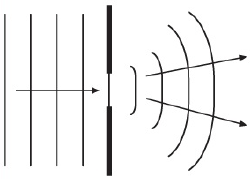
11) a: Explain what is meant by the diffraction of a wave. [2]
b: This diagram shows waves, in a ripple tank, spreading out from two slits.
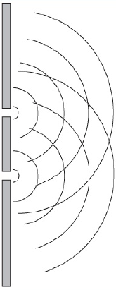
Copy this diagram. On your diagram, sketch:
i- a line showing points along the central maximum–label this line 0 [1]
ii- a line showing the points along first maximum–label this line 1 [1]
iii- a line showing points along one of the first minima–label this line min. [1]
c: The centres of the slits are $12 cm$ apart. At a distance of $60 cm$ from the barrier, the first maxima are $18 cm$ either side of the central maximum.
Calculate the wavelength of the waves. (You may assume that the doubleslit equation developed for light is applicable to ripples.) [3]
[Total: 8]
SELF-EVALUATION CHECKLIST
After studying this chapter, complete a table like this:
| I can | See topic… | Needs more work | Almost there | Ready to move on |
| understand the principle of superposition | 13.1 | |||
| understand diffraction, interference, path difference and coherence | 13.2, 13.3 | |||
| understand the conditions for constructive and destructive interference | 13.3 | |||
| understand experiments involving two coherent sources | 13.3 | |||
| recall and use $\lambda = \frac{{ax}}{D}$ for double-slit interference using light | 13.4 | |||
| recall and use $\theta = n\lambda $ for a diffraction grating | 13.5 | |||
| use a diffraction grating to determine the wavelength of light. | 13.5 |