Physics A Level
P1 Practical skills at AS Level P1.2 Using apparatus and following instructions
Physics A Level
P1 Practical skills at AS Level P1.2 Using apparatus and following instructions
- Chapter 1: Kinematics
- Chapter 2: Accelerated motion
- Chapter 3: Dynamics
- Chapter 4: Forces
- Chapter 5: Work, energy and power
- Chapter 6: Momentum
- Chapter 7: Matter and materials
- Chapter 8: Electric current
- Chapter 9: Kirchhoff’s laws
- Chapter 10: Resistance and resistivity
- Chapter 11: Practical circuits
- Chapter 12: Waves
- Chapter 13: Superposition of waves
- Chapter 14: Stationary waves
- Chapter 15: Atomic structure
- P1 Practical skills at AS Level
- Chapter 16: Circular motion
- Chapter 17: Gravitational fields
- Chapter 18: Oscillations
- Chapter 19: Thermal physics
- Chapter 20: Ideal gases
- Chapter 21: Uniform electric fields
- Chapter 22: Coulomb’s law
- Chapter 23: Capacitance
- Chapter 24: Magnetic fields and electromagnetism
- Chapter 25: Motion of charged particles
- Chapter 26: Electromagnetic induction
- Chapter 27: Alternating currents
- Chapter 28: Quantum physics
- Chapter 29: Nuclear physics
- Chapter 30: Medical imaging
- Chapter 31: Astronomy and cosmology
- P2 Practical skills at A Level
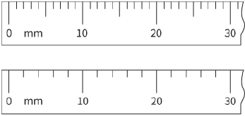
When using measuring instruments like these you need to ensure that you are fully aware of what each division on a scale represents. If you look at Figure P1.1 you will see that on the first ruler each division is $1 mm$, and on the second each division is $2 mm$.
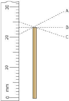
If you use instruments incorrectly, you may introduce errors into your readings. For example, when taking a reading your line of sight should always be perpendicular to the scale that you are using. Otherwise, you will introduce a parallax error; this is shown in Figure P1.2. Looking from point A the length of the rod appears to be $21 mm$, from point C it appears to be $25 mm$ and from point B, the correct position, the length is $23 mm$.
represents
A rule, for example, a metre rule, or a ruler, for example, an ordinary school ruler of length $30 cm$, are simple measuring instruments with a smallest division of $1 mm$. Other instruments have a greater precision because their smallest scale division is less than $1 mm$. Here, we will look at two of them.
Calipers
Calipers are designed to grip an object with two jaws and, in the example shown in Figure P1.3, to measure the diameter of the object. They can also be used to measure the internal diameter of a tube, for example, if the two prongs are placed inside the tube and the moving part of the calipers is adjusted until the prongs just grip the inside of the tube.
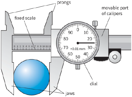
The calipers shown in Figure P1.3 are dial calipers, although other versions such as vernier calipers are still sometimes used. As the sliding scale moves along, one rotation of the dial moves the jaws $1 mm$ further apart. Since the dial shown has 100 divisions, each of these divisions is $\frac{1}{{100}} = 0.10\,mm$. The object shown has a diameter of $12 mm$ on the fixed scale and 25 divisions or $0.25 mm$ on the dial, so the diameter of the object is $12.25 mm$.
Micrometer screw gauge
A micrometer screw gauge, or more simply a micrometer, is shown in Figure P1.4. This also has two scales. The main scale is on the shaft and the fractional scale is on the rotating barrel. One rotation of the barrel moves the end of the barrel $0.50 mm$ along the shaft. The barrel has 50 divisions so each division represents $\frac{{0.50}}{{50}} = 0.01\,mm$.
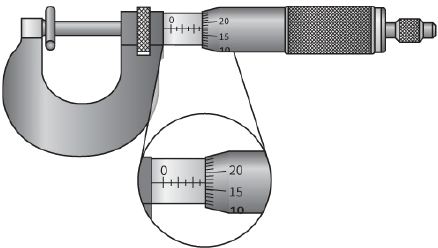
To use the micrometer, turn the barrel until the jaws just tighten on the object. Some micrometers have a ratchet or slip mechanism to prevent the user from tightening too hard and damaging the micrometer or object. Read the main scale to the nearest $0.5 mm$, then read the number of divisions on the sleeve, which
will be in $0.01 mm$, and finally add the two readings. You should realise that the smallest division on the micrometer is $0.01 mm$.
Before you start to use a micrometer or dial calipers, it is usual to check if there is a zero error. This is done by bringing the jaws together without any object between them. Obviously, the reading should be zero, but if the instrument is worn or has been used badly the reading may not be zero. When you have taken this zero error reading, it should be added to or subtracted from every other reading that you take with the instrument. If the jaws do not quite close to the zero mark, there is a positive zero error, and this zero error reading should be subtracted. The zero error is an example of a systematic error, which is dealt with later in this chapter.
It is also important that you become familiar with setting up apparatus. When instructions are given, the only way to become confident is through practice. You may face a variety of tasks, from setting up a pendulum system to measuring the angle at which a tilted bottle falls.
You should also learn to set up simple circuits from circuit diagrams. The most common error in building circuits comes where components need to be connected in parallel. A good piece of advice here is to build the main circuit first, and then add the components that need to be connected in parallel.