Physics A Level
Chapter 23: Capacitance 23.1 Capacitors in use
Physics A Level
Chapter 23: Capacitance 23.1 Capacitors in use
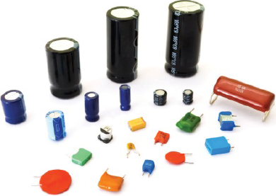
Capacitors are used to store energy in electrical and electronic circuits. This means that they have many valuable applications. For example, capacitors are used in computers; they store energy in normal use and then they gradually release this energy if there is a power failure, so that the computer will operate long enough to save valuable data. Figure 23.2 shows a variety of shapes and sizes of capacitors.
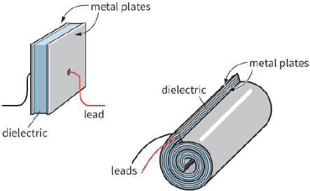
Every capacitor has two leads, each connected to a metal plate. To store energy, these two plates must be given equal and opposite electric charges. Between the plates is an insulating material called the dielectric. Figure 23.3 shows a simplified version of the construction of a capacitor; in practice, many have a spiral form.
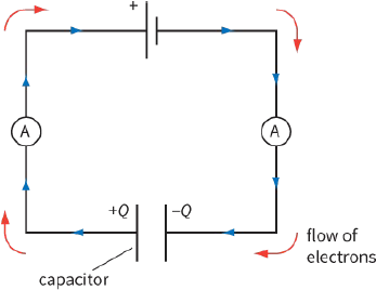
To move charge onto the plates of a capacitor, it must be connected to a voltage supply. The negative terminal of the supply pushes electrons onto one plate, making it negatively charged. Electrons are repelled from the other plate, making it positively charged. Figure 23.4 shows that there is a flow of electrons all the way round the circuit.
The two ammeters will give identical readings. The current stops when the potential difference (p.d.)
across the capacitor is equal to the electromotive force (e.m.f.) of the supply. We then say that the capacitor is ‘fully charged’.
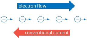
Note: The convention is that current is the flow of positive charge. Here, it is free electrons that flow.
Electrons are negatively charged; conventional current flows in the opposite direction to the electrons (Figure 23.5).
Charge on the plates
Think about a capacitor with uncharged plates. Each plate has equal amounts of positive and negative charge. Connecting the capacitor to a supply pulls charge $+Q$ from one plate and transfers it to the other, leaving behind charge $−Q$. The supply does work in separating the charges. Since the two plates now store equal and opposite charges, the total charge on the capacitor is zero. When we talk about the ‘charge stored’ by a capacitor, we mean the quantity Q, the magnitude of the charge stored on each plate.
To make the capacitor plates store more charge, we would have to use a supply of higher e.m.f. If we connect the leads of the charged capacitor together, electrons flow back around the circuit and the capacitor is discharged.
You can observe a capacitor discharging as follows. Connect the two leads of a capacitor to the terminals of a battery. Disconnect, and then reconnect the leads to a light-emitting diode (LED). It is best to have a protective resistor in series with the LED. The LED will glow briefly as the capacitor discharges.
In any circuit, the charge that flows past a point in a given time is equal to the area under a current–time graph (just as distance is equal to the area under a speed–time graph). So the magnitude of the charge on the plates in a capacitor is given by the area under the current–time graph recorded while the capacitor is being charged up.
The meaning of capacitance
If you look at some capacitors, you will see that they are marked with the value of their capacitance. The greater the capacitance, the greater is the charge on the capacitor plates for a given potential difference across it.
The capacitance C of a capacitor is defined by:
$\begin{array}{l}
capacitance = \frac{{charge}}{{potental\,difference}}\\
C = \frac{Q}{V}
\end{array}$
where Q is the magnitude of the charge on each of the capacitor’s plates and V is the potential difference across the capacitor.
The charge on the capacitor may be calculated using the equation:
$Q = VC$
This equation shows that the charge depends on two things: the capacitance C and the voltage V (double the voltage means double the charge). Note that it isn’t only capacitors that have capacitance. Any object can become charged by connecting it to a voltage. The object’s capacitance is then the ratio of the charge to the voltage.
Units of capacitance
The unit of capacitance is the farad, F. From the equation that defines capacitance, you can see that this must be the same as the units of charge (coulombs, C) divided by voltage (V):
$1F = 1C\,{V^{ - 1}}$
(It is unfortunate that the letter ‘C’ is used for both capacitance and coulomb. There is room for confusion here!)
In practice, a farad is a large unit. Few capacitors have a capacitance of $1 F$. Capacitors usually have their
values marked in picofarads (pF), nanofarads (nF) or microfarads ($\mu F$):
$1\,pF = {10^{ - 12}}F$
$1\,nF = {10^{ - 9}}F$
$1\,\mu F = {10^{ - 6}}F$
Other markings on capacitors
Many capacitors are marked with their highest safe working voltage. If you exceed this value, charge may leak across between the plates, and the dielectric will cease to be an insulator. Some capacitors (electrolytic ones) must be connected correctly in a circuit. They have an indication to show which end must be connected to the positive of the supply. Failure to connect correctly will damage the capacitor, and can be extremely dangerous.
Questions
1) Calculate the charge on a $220\,\mu F$ capacitor charged up to $15 V$. Give your answer in microcoulombs ($\mu C$) and in coulombs (C).
2) A charge of $1.0 \times {10^{ - 3}}\,C$ is measured on a capacitor with a potential difference across it of $500 V$.
3) Calculate the capacitance in farads (F), microfarads ($\mu F$) and picofarads (pF).
Calculate the average current required to charge a $50\,\mu F$ capacitor to a p.d. of $10 V$ in a time interval of $0.01 s$.
4) A student connects an uncharged capacitor of capacitance C in series with a resistor, a cell and a switch. The student closes the switch and records the current I at intervals of $10 s$. The results are shown in Table 23.1. The potential difference across the capacitor after $60 s$ is $8.5 V$. Plot a current–time graph, and use it to estimate the value of C.
| 60 | 50 | 40 | 30 | 20 | 10 | 0 | $t/s$ |
| 27 | 37 | 51 | 75 | 102 | 142 | 200 | $I/\mu A$ |