Physics A Level
Chapter 23: Capacitance 23.2 Energy stored in a capacitor
Physics A Level
Chapter 23: Capacitance 23.2 Energy stored in a capacitor
When you charge a capacitor, you use a power supply to push electrons onto one plate and off the other.
The power supply does work on the electrons, so their potential energy increases. You recover this energy when you discharge the capacitor.
If you charge a large capacitor ($1000\,\mu F$ or more) to a potential difference of $6.0 V$, disconnect it from the supply and then connect it across a $6.0 V$ lamp, you can see the lamp glow as energy is released from the capacitor. The lamp will flash briefly. Clearly, such a capacitor does not store much energy when it is charged.
In order to charge a capacitor, work must be done to push electrons onto one plate and off the other (Figure 23.6). At first, there is only a small amount of negative charge on the left-hand plate. Adding more electrons is relatively easy, because there is not much repulsion. As the charge on the plate increases, the repulsion between the electrons on the plate and the new electrons increases, and a greater amount of work must be done to increase the charge on the plate.
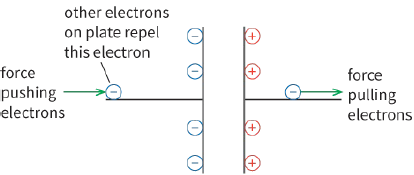
.repulsion of the electrons that are already present
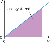
This can be seen qualitatively in Figure 23.7a. This graph shows how the p.d. V increases as the amount of charge Q increases. It is a straight line because Q and V are related by:
$V = \frac{Q}{C}$
We can use Figure 23.7a to calculate the work done in charging up the capacitor.
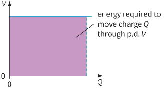
First, consider the work done W in moving charge Q through a constant p.d. V. This is given by:
$W = QV$
(You studied this equation in Chapter 9.) From the graph of Q against V (Figure 23.7b), we can see that the quantity $Q \times V$ is given by the area under the graph.
The area under a graph of p.d. against charge is equal to work done.
If we apply the same idea to the capacitor graph (Figure 23.7a), then the area under the graph is the shaded triangle, with an area of base × height. Hence, the work done in charging a capacitor to a particular p.d. is given by:
$W = \frac{1}{2}QV$
Substituting $Q = CV$ into this equation gives two further equations:
$\begin{array}{l}
W = \frac{1}{2}C{V^2}\\
W = \frac{1}{2}\frac{{{Q^2}}}{C}
\end{array}$
|
|
where W energy stored, Q is the charge on the capacitor, C is the capacitance and V is the potential difference across the capacitor.
These three equations show the work done in charging up the capacitor. This is equal to the energy stored by the capacitor, since this is the amount of energy released when the capacitor is discharged.
We can also see from the second formula ($W = \frac{1}{2}\,C{V^2}$) that the energy W that a capacitor stores depends on its capacitance C and the potential difference V to which it is charged.
The energy W stored is proportional to the square of the potential difference $V(W \propto {V^2})$. It follows that doubling the charging voltage means that four times as much energy is stored.
Questions
5) State the quantity represented by the gradient of the straight line shown in Figure 23.7a.
6) The graph of Figure 23.8 shows how V depends on Q for a particular capacitor.

The area under the graph has been divided into strips to make it easy to calculate the energy stored.
The first strip (which is simply a triangle) shows the energy stored when the capacitor is charged up to $1.0 V$. The energy stored is:
$\begin{array}{l}
\frac{1}{2}QV = \frac{1}{2} \times 1.0\,mC \times 1.0\,V\\
= 0.5\,mJ
\end{array}$
a: Calculate the capacitance C of the capacitor.
b: Copy Table 23.2 and complete it by calculating the areas of successive strips, to show how W depends on V.
c: Plot a graph of W against V. Describe the shape of this graph.
| $Q / mC$ | $V / V$ | Area of strip $\Delta W/mg$ | Sum of areas $W / mJ$ |
| 1.0 | 1.0 | 0.5 | 0.5 |
| 2.0 | 2.0 | 1.5 | 2.0 |
| 3.0 | |||
| 4.0 |
PRACTICAL ACTIVITY 23.1
Investigating energy stored in a capacitor
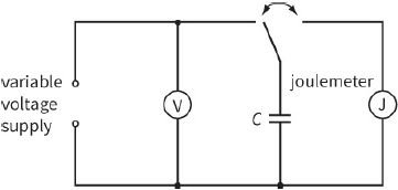
If you have a sensitive joulemeter (capable of measuring millijoules, mJ), you can investigate the equation for energy stored. A suitable circuit is shown in Figure 23.9.
The capacitor is charged up when the switch connects it to the power supply. When the switch is altered, the capacitor discharges through the joulemeter. (It is important to wait for the capacitor to discharge completely.) The joulemeter will measure the amount of energy released by the capacitor.
By using capacitors with different values of C, and by changing the charging voltage V, you can investigate how the energy W stored depends on C and V.
Questions
7) Calculate the energy stored in the following capacitors:
a: a $5000\,\mu F$ capacitor charged to $5.0 V$
b: a $5000 pF$ capacitor charged to $5.0 V$
c: a $200\,\mu F$ capacitor charged to $230 V$.
8) Which involves more charge, a $100\,\mu F$ capacitor charged to $200 V$ or a $200\,\mu F$ capacitor charged to $100 V$? Which stores more energy?
9) A $10000\,\mu F$ capacitor is charged to $12 V$, and then connected across a lamp rated at ‘$12 V, 36 W$’.
a: Calculate the energy stored by the capacitor.
b: Estimate the time the lamp stays fully lit. Assume that energy is dissipated in the lamp at a steady rate.
10) In a simple photographic flashgun, a $0.20 F$ capacitor is charged by a $9.0 V$ battery. It is then discharged in a flash of duration $0.01 s$. Calculate:
a: the charge on and energy stored by the capacitor
b: the average power dissipated during the flash
c: the average current in the flash bulb
d: the approximate resistance of the bulb.