Physics A Level
Chapter 24: Magnetic fields and electromagnetism 24.4 Measuring magnetic flux density
Physics A Level
Chapter 24: Magnetic fields and electromagnetism 24.4 Measuring magnetic flux density
Practical Activity 24.2 looks at two practical methods for measuring magnetic flux density
PRACTICAL ACTIVITY 24.2 MEASURING MAGNETIC FLUX DENSITY
Measuring B with a Hall probe
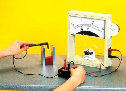
The simplest device for measuring magnetic flux density B is a Hall probe (Figure 24.12). When the probe is held so that the field lines are passing at right angles through the flat face of the probe, the meter gives a reading of the value of B. Some instruments are calibrated so that they give readings in microteslas ($\mu T$) or milliteslas (mT). Others are not calibrated, so you must either calibrate them or use them to obtain relative measurements of B.
A Hall probe must be held so that the field lines are passing directly through it, at right angles to the flat surface of the probe (Figure 24.13). If the probe is not held in the correct orientation, the reading on the meter will be reduced.
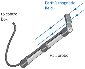
A Hall probe is sensitive enough to measure the Earth’s magnetic flux density. The probe is first held so that the Earth’s field lines are passing directly through it, as shown in Figure 24.13. In this orientation, the reading on the voltmeter will be a maximum. The probe is then rotated through ${180^ \circ }$ so that the magnetic field lines are passing through it in the opposite direction. The change in the reading of the meter is twice the Earth’s magnetic flux density. There is more about how the Hall probe works in Chapter 25.
Measuring B with a current balance
Figure 24.14 shows a simple arrangement that can be used to determine the flux density between two magnets. The magnetic field between these magnets is (roughly) uniform. The length L of the currentcarrying wire in the uniform magnetic field can be measured using a ruler.
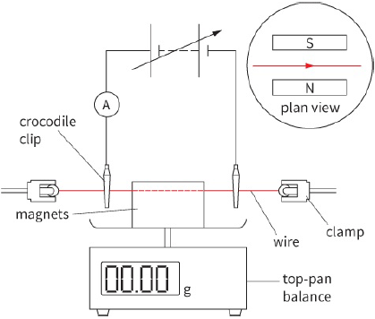
When there is no current in the wire, the magnet arrangement is placed on the top pan and the balanceis zeroed. Now, when a current I flows in the wire, its value is shown by the ammeter. The wire experiences an upward force and, according to Newton’s third law of motion, there is an equal and opposite force on the magnets. The magnets are pushed downwards and a reading appears on the scale of the balance. The force F is given by mg, where m is the mass indicated on the balance in kilograms and g is the acceleration of free fall ($9.81\,m\,{s^{ - 2}}$).
Knowing F, I and L, the magnetic flux density B between the magnets can be determined using the equation:
You can also use the arrangement in Figure 24.14 to show that the force is directly proportional to the current.
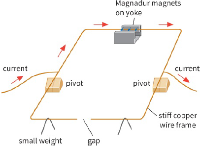
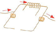
A system like this in effect ‘weighs’ the force on the current-carrying conductor, and is an example of a current balance. Another version of a current balance is shown in Figure 24.15. This consists of a wire frame that is balanced on two pivots. When a current flows through the frame, the magnetic field pushes the frame downwards. By adding small weights to the other side of the frame, you can restore it to a balanced position.
Questions
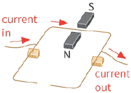
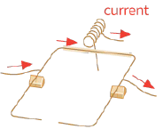
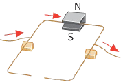
8) In the examples shown in the diagrams in Figure 24.16, which current balances will tilt? Will the side carrying the current tilt upwards or downwards?
|
|
|
|
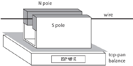
9) In the arrangement shown in Figure 24.17, the balance reading changes from $102.48 g$ to $104.48 g$ when the current is switched on. Explain why this happens and give the direction and the size of the force on the wire when the current is on. What is the direction of the current in the wire?