Physics A Level
Chapter 25: Motion of charged particles 25.4 The Hall effect
Physics A Level
Chapter 25: Motion of charged particles 25.4 The Hall effect
In Chapter 24, you saw how to use a Hall probe to measure magnetic flux density. This probe works on the basis of the Hall effect. The Hall effect is the production of a potential difference across an electrical conductor when an external magnetic field is applied in a direction perpendicular to the current.
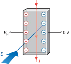
Consider a slice of conductor with an external magnetic field applied perpendicular to the direction of the current. If the conductor is a metal, then the current is due to the flow of electrons. These electrons will experience a magnetic force, which will make them drift towards one side of the conductor, where they will gather. The opposite side of the slice is deficient of electrons. A potential difference, known as the Hall voltage, will be developed across the conductor (Figure 25.12). As you will see later, the Hall voltage VH for the slice is constant for a given current and is directly proportional to the magnetic flux density B of the external magnetic field.
An equation for the Hall voltage
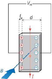
Using what we know about electric current and the forces on electric charges produced by electric and magnetic fields, we can derive an expression for the Hall voltage VH. Figure 25.13 shows a currentcarrying slice of a metal. The Hall voltage is the voltage that appears between the two opposite sides of the slice.
|
|
As we have seen, this voltage arises because electrons accumulate on one side of the slice. There is a corresponding lack of electrons on the opposite side – this opposite side may be considered to have a positive charge. As a result, there is an electric field set up within the slice between the two sides. The two charged sides may be treated as oppositely charged parallel plates – see Chapter 21. Therefore, the electric field strength E is related to the Hall voltage ${V_H}$ by:
$E = \frac{{{V_H}}}{d}$
where d is the width of the slice.
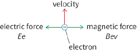
Now, imagine a single electron as it travels with drift velocity v through the slice. The magnetic field is into the plane of the paper, so this electron will experience a magnetic force Bev to the right. It will also experience an electric force Ee to the left.
When the current first starts to flow, there is no Hall voltage and so electrons are pushed to the right by the magnetic field. However, as the charge on the right-hand side builds up, so does the internal electric field and this pushes the electrons in the opposite direction to the magnetic force. Soon, an equilibrium situation is reached, the resultant force on each electron is zero and the electrons are undeflected. Now we can equate the two forces:
$eE = Bev$
Substituting for E we have:
$\frac{{e{V_H}}}{d} = Bev$
Now recall from Chapter 8 that the current I is related to the mean drift velocity v of the electrons by $I =nAve$, where A is the cross-sectional area of the conductor and n is the number density of charge carriers (in this case, electrons). So, we can substitute for v to get:
$\frac{{e{V_H}}}{d} = \frac{{BeI}}{{nAe}}$
Making VH the subject of the equation (and cancelling e) gives:
${V_H} = \frac{{BId}}{{nAe}}$
The cross-sectional area A of each side-face of the slice is:
$A = d \times t$
where t is the thickness of the slice.
Substituting and cancelling gives:
${V_H} = \frac{{BI}}{{nte}}$
This equation for the Hall voltage shows that ${V_H}$ is directly proportional to the magnetic flux density B for a given slice and current. That is what makes the Hall effect so useful for measuring B.
To get a large voltage, it would be desirable to have a material with a smaller value for n compared with metals. Hall probes use a very thin slice of semiconductor. Semiconductors have a number density many thousands of times smaller than metals, hence the Hall voltage will be thousands of times larger.
In some semiconductors, the charge carriers are not electrons, but positively charged particles referred to as ‘holes’. We can write a more general equation for the Hall voltage replacing e with q, where q is the charge of an individual charge carrier. This gives ${V_H} = \frac{{BI}}{{ntq}}$.
Positive charges will be deflected in the opposite direction to negative charges, and so we can determine whether the charge carriers are positive or negative by the sign of the Hall voltage.
Questions
8) A Hall probe is designed to operate with a steady current of $0.020 A$ in a semiconductor slice of thickness $0.05 mm$. The number density of charge carriers (electrons) in the semiconductor is $1.5 \times {10^{23}}\,{m^{ - 3}}$
a: Calculate the Hall voltage that will result when the probe is placed at right angles to a magnetic
field of flux density $0.10 T$.
(Elementary charge $e = 1.60 \times {10^{ - 19}}\,C$.)
b: Explain why the current in the Hall probe must be maintained at a constant value.
9) Suggest how the Hall effect could be used to determine the number density of charge carriers n in a semiconducting material.