Physics A Level
Chapter 26: Electromagnetic induction 26.2 Explaining electromagnetic induction
Physics A Level
Chapter 26: Electromagnetic induction 26.2 Explaining electromagnetic induction
You have seen that relative movement of a conductor and a magnetic field induces a current in the conductor when it is part of a complete circuit. In the experiments in Practical Activity 26.1, the meter was used to complete the circuit. Now we need to think about how to explain these observations, using what we know about magnetic fields.
Cutting magnetic field lines
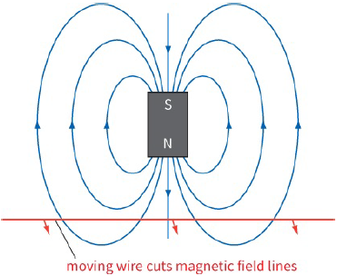
Start by thinking about a simple bar magnet. It has a magnetic field in the space around it. We represent this field by magnetic field lines. Now think about what happens when a wire is moved into the magnetic field (Figure 26.5). As it moves, it cuts across the magnetic field. Remove the wire from the field, and again it must cut across the field lines, but in the opposite direction.
We think of this cutting of a magnetic field by a conductor as the effect that gives rise to current caused by induced e.m.f in the conductor. It doesn’t matter whether the conductor is moved through the magnetic field or the magnet is moved past the conductor, the result is the same–there will be an induced e.m.f.
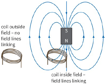
The effect is more noticeable if we use a coil of wire. For a coil of N turns, the effect is N times greater than for a single turn of wire. With a coil, it is helpful to imagine the number of field lines linking the coil.
If there is a change in the number of field lines that pass through the coil, an e.m.f. will be induced across the ends of the coil (or there will be a current caused by induced e.m.f if the coil forms part of a complete circuit).
Figure 26.6 shows a coil near a magnet. When the coil is outside the field, there are no magnetic field lines linking the coil. When it is inside the field, field lines link the coil. Moving the coil into or out of the field changes this linkage of field lines, and this induces an e.m.f. across the ends of the coil. Field lines linking the coil is a helpful starting point in our understanding of induced e.m.f. However, as you will see later, a more sophisticated idea of magnetic flux is required for a better understanding of how an e.m.f. is generated in a circuit.
Question
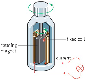
1) Use the idea of a conductor cutting magnetic field lines to explain how a current is caused by induced e.m.f. in a bicycle generator (Figure 26.7).
Current direction (extension)
How can we predict the direction of the current caused by induced e.m.f? For the motor effect in Chapter 24, we used Fleming’s left-hand (motor) rule. Electromagnetic induction is like the mirror image of the motor effect. Instead of a current producing a force on a current-carrying conductor in a magnetic field, we provide an external force on a conductor by moving it through a magnetic field and this induces a current in the conductor. So you should not be too surprised to find that we use the mirror image of the left-hand rule: Fleming’s right-hand (generator) rule.
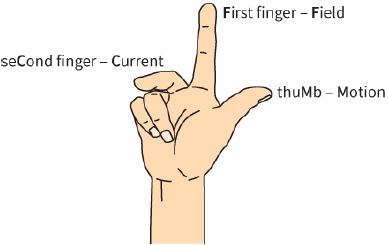
The three fingers represent the same things again (Figure 26.8):
- thuMb–direction of Motion
- First finger–direction of external magnetic Field
- seCond finger–direction of (conventional) Current caused by induced e.m.f
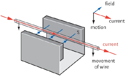
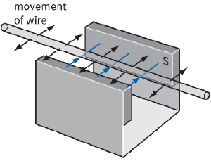
In the example shown in Figure 26.9, the conductor is being moved downwards across the magnetic field.
There is a current caused by induced e.m.f. in the conductor as shown. Check this with your own right hand. You should also check that reversing the movement or the field will result in the current flowing in the opposite direction.
Induced e.m.f.
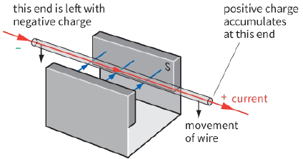
When a conductor is not part of a complete circuit, there cannot be a current induced by e.m.f. Instead, negative charge will accumulate at one end of the conductor, leaving the other end positively charged. We have induced an e.m.f. across the ends of the conductor.
Is e.m.f. the right term? Should it be potential difference (voltage)? In Chapter 8, you saw the distinction between voltage and e.m.f. The term e.m.f. is the correct one here because, by pushing the wire through the magnetic field, work is done and this is transformed into electrical energy. Think of this in another way: since we could connect the ends of the conductor so that there is a current in some other component, such as a lamp, which would light up, it must be an e.m.f. $– a$ source of electrical energy.
Figure 26.10 shows how an e.m.f. is induced. Notice that, within the conductor, conventional current is from negative to positive, in the same way as inside a battery or any other source of e.m.f. In reality, the free electrons within the conductor travel from right to left, making the left-hand side of the conductor negative. What causes these electrons to move? Moving the conductor is equivalent to giving a free electron within the conductor a velocity in the direction of this motion. This electron is in an external magnetic field and hence experiences a magnetic force Bev from right to left. Check this out for yourself.
Questions
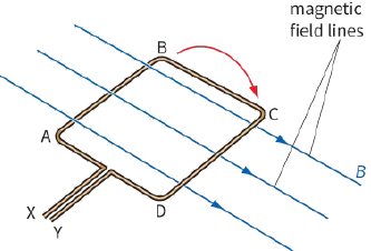
2) The coil in Figure 26.11 is rotating in a uniform magnetic field.
Predict the direction of the current caused by induced e.m.f. in sections AB and CD.
State which terminal, X or Y, will become positive.
3) When an aircraft flies from east to west, its wings are an electrical conductor cutting across the Earth’s magnetic flux. In the northern hemisphere, state which wingtip (left or right) will become positive.
State and explain what will happen to this wingtip in the southern hemisphere.
Magnetic flux and magnetic flux linkage
So far, in this chapter we have looked at the ideas of electromagnetic induction in a very descriptive manner. Now we will see how to calculate the value of the induced e.m.f. and look at a general way of determining its direction.
In Chapter 24, we saw how magnetic flux density B is defined by the equation $B = \frac{F}{{IL}}$
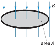
Now we can go on to define magnetic flux as a quantity. We picture magnetic flux density B as the number of magnetic field lines passing through a region per unit area. Similarly, we can picture magnetic flux as the total number of magnetic field lines passing through a cross-sectional area A. For a magnetic field normal to A, the magnetic flux $\Phi $ (Greek letter phi) must therefore be equal to the product of magnetic flux density and the area A (Figure 26.12a).
|
|
The magnetic flux $\Phi $ through cross-sectional area A is defined as:
$\Phi = BA$
where B is the component of the magnetic flux density perpendicular to the area.
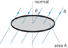
How can we calculate the magnetic flux when B is not perpendicular to A? You can easily see that when the field is parallel to the plane of the area, the magnetic flux through A is zero. To find the magnetic flux in general, we need to find the component of the magnetic flux density perpendicular to the crosssectional area. Figure 28.12b shows a magnetic field at an angle $\theta $ to the normal. In this case:
$magnetic\,flux\,\Phi \,(B\,\cos \theta ) \times A$
or simply:
$magnetic\,flux\,\Phi \,BA\,\cos \theta $
(Note that, when $\theta = {90^ \circ }$, $\Phi = 0$ and when $\theta = {0^ \circ }\,\Phi = BA$)
For a coil with N turns, the magnetic flux linkage is defined as the product of the magnetic flux and the number of turns; that is:
$magnetic\,flux\,linkage = N\Phi \,$
or
$magnetic\,flux\,linkage = BAN\cos \theta \,$
The unit for magnetic flux, and magnetic flux linkage is the weber (Wb).
One weber (1 Wb) is the magnetic flux that passes perpendicularly through a cross-section of area $1\,{m^2}$ when the magnetic flux density is $1\,T.1Wb = 1T{m^2}$.
An e.m.f. is induced in a circuit whenever magnetic flux linking the circuit changes with respect to time.
Since magnetic flux is equal to $BA\cos \theta $, there are three ways an e.m.f. can be induced:
- changing the magnetic flux density B
- changing the cross-sectional area A of the circuit
- changing the angle$\theta $.
Now look at Worked example 1.
Questions
4) Use the idea of magnetic flux linkage to explain why, when a magnet is moved into a coil, the e.m.f.
induced depends on the strength of the magnet and the speed at which it is moved.
5) In an experiment to investigate the factors that affect the magnitude of an induced e.m.f., a student moves a wire back and forth between two magnets, as shown in Figure 26.14. State why the e.m.f.
generated in this way is almost zero.
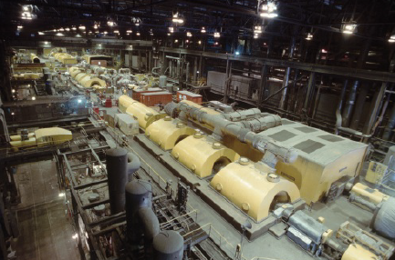
6) In the type of generator found in a power station (Figure 26.15), a large electromagnet is made to rotate inside a fixed coil. An e.m.f. of $25 kV$ is induced; this is an alternating voltage of frequency $50Hz$.
a: State the factor that determines the frequency.
b: Suggest the factors that you think would affect the magnitude of the induced e.m.f.
7) At the surface of the north pole of a bar magnet, the magnetic field is uniform with flux density $0.15 T$.
The pole has dimensions $1.0\,cm \times 1.5\,cm$.
Calculate the magnetic flux at this pole.
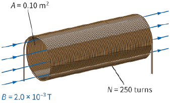
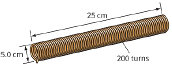
8) A solenoid has diameter $5.0 cm$, length $25 cm$ and 200 turns of wire (Figure 26.16). A current of $2.0 A$ creates a uniform magnetic field of flux density $2.0 \times {10^{ - 5}}T$ through the core of this solenoid.
a: Calculate the magnetic flux linkage for this solenoid.
b: The diameter of the solenoid is $5.0 \pm 0.2\,cm$. Determine the absolute uncertainty in value calculated in part a. You may assume all the other quantities have negligible uncertainties.
9) A rectangular coil with 120 turns is placed at right angles to a magnetic field of flux density $1.2 T$. The coil has dimensions $5.0\,cm \times 7.5\,cm$.
Calculate the magnetic flux linkage for this coil.