Physics A Level
Chapter 26: Electromagnetic induction 26.4 Lenz’s law
Physics A Level
Chapter 26: Electromagnetic induction 26.4 Lenz’s law
We use Faraday’s law to calculate the magnitude of an induced e.m.f. Now, we can go on to think about the direction of the induced e.m.f. – in other words, which end of a wire or coil moving in a magnetic field becomes positive, and which becomes negative.
Fleming’s right-hand rule gives the direction of a current caused by induced e.m.f. This is a particular case of a more general law, Lenz’s law, which will be explained in this topic. First, we will see how the motor effect and the generator effect are related to each other.
The origin of electromagnetic induction
So far, we have not given an explanation of electromagnetic induction. You have seen, from the experiments at the beginning of this chapter, that it does occur, and you know the factors that affect it.
But what is the origin of the current?
Figure 26.20 gives an explanation. A straight metal wire XY is being pushed downwards through a horizontal magnetic field of flux density B. Now, think about the free electrons in the wire. They are moving downwards, so they are, in effect, an electric current. Of course, because electrons are negatively charged, the conventional current is flowing upwards.
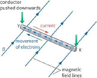
We now have a current flowing across a magnetic field, and the motor effect will, therefore, come into play. Each electron experiences a force of magnitude Bev. Using Fleming’s left-hand rule, we can find the direction of the force on the electrons. The diagram shows that the electrons will be pushed in the direction from X to Y. So a current has been induced to flow in the wire; the direction of the conventional current is from Y to X.
Now, we can check that Fleming’s right-hand rule gives the correct directions for motion, field and current, which indeed it does.
So, to summarise, there is a current caused by the induced e.m.f. current because the electrons are pushed by the motor effect. Electromagnetic induction is simply a consequence of the motor effect.
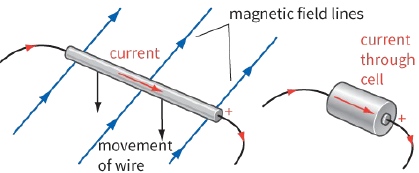
In Figure 26.20, electrons are found to accumulate at Y. This end of the wire is thus the negative end of the e.m.f. and X is positive. If the wire was connected to an external circuit, electrons would flow out of Y, round the circuit, and back into X. Figure 26.21 shows how the moving wire is equivalent to a cell (or any other source of e.m.f.).
Forces and movement
Electromagnetic induction is how we generate most of our electricity. We turn a coil in a magnetic field, and the mechanical energy we put in is transferred to electrical energy. By thinking about these energy transfers, we can deduce the direction of the current.
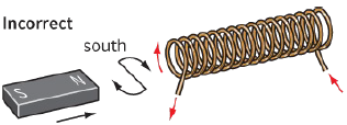
Figure 26.22 shows one of the experiments from earlier in this chapter. The north pole of a magnet is being pushed towards a coil of wire. There is a current in the coil, but what is its direction? The diagram shows the two possibilities.
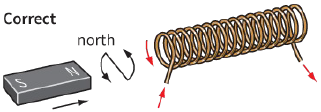
Figure 26.22: Moving a magnet towards a coil: the direction of the current caused by the induced e.m.f.
is as shown in b, not a.
|
|
The current in the coil makes it into an electromagnet. One end becomes the north pole, the other the south pole. In Figure 26.22a, if the current is in this direction, the coil end nearest the approaching north pole of the magnet would be a south pole. These poles will attract one another, and you could gently let go of the magnet and it would be dragged into the coil. The magnet would accelerate into the coil, the current caused by induced e.m.f. would increase further, and the force of attraction between the two would also increase.
In this situation, we would be putting no (or very little at the start) energy into the system, but the magnet would be gaining kinetic energy, and the current would be gaining electrical energy. A nice trick if you could do it, but this would violate the principle of conservation of energy!
Figure 26.22b shows the correct situation. As the north pole of the magnet is pushed towards the coil, the current caused by the induced e.m.f. makes the end of the coil nearest the magnet become a north pole.
The two poles repel one another, and you have to do work to push the magnet into the coil. The energy transferred by your work is transferred to electrical energy of the current. The principle of energy conservation is not violated in this situation.
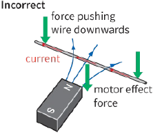
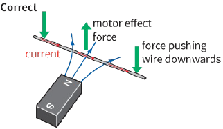
Figure 26.23 shows how we can apply the same reasoning to a straight wire being moved in a downward direction through a magnetic field. There will be a current caused by induced e.m.f. in the wire, but in which direction? Since this is a case of a current across a magnetic field, a force will act on it (the motor effect), and we can use Fleming’s left-hand rule to deduce its direction.
|
|
First, we will consider what happens if the current caused by the induced e.m.f. is in the wrong direction.
This is shown in Figure 26.23a. The left-hand rule shows that the force that results would be downward–in the direction in which we are trying to move the wire. The wire would thus be accelerated, the current would increase and again we would be getting both kinetic and electrical energy for no energy input.
The current must be as shown in Figure 26.23b. The force that acts on it due to the motor effect pushes against you as you try to move the wire through the field. You have to do work to move the wire, and hence to generate electrical energy. Once again, the principle of energy conservation is not violated.
Questions
13) Use the ideas in the previous topic to explain what happens if a you stop pushing the magnet towards the coil shown in Figure 26.22, and b you pull the magnet away from the coil.
14) Draw a diagram to show the directions of the current caused by induced e.m.f. and of the opposing force if you now try to move the wire shown in Figure 26.23 upwards through the magnetic field.
A general law for induced e.m.f.
Lenz’s law summarises this general principle of energy conservation. The direction of a current caused by induced e.m.f. or e.m.f is such that it always produces a force that opposes the motion that is being used to produce it. If the direction of the e.m.f were opposite to this, we would be getting energy for nothing.
Here is a statement of Lenz’s law:
Any induced e.m.f. will be established in a direction so as to produce effects that oppose the change that is producing it.
This law can be shown to be correct in any experimental situation. For example, in Figure 26.3, a sensitive ammeter connected in the circuit shows the direction of the current as the magnet is moved in and out. If a battery is later connected to the coil to make a larger and constant current in the same direction, a compass will show what the poles are at the end of the solenoid. If a north pole is moved into the solenoid, then the solenoid itself will have a north pole at that end. If a north pole is moved out of the solenoid, then the solenoid will have a south pole at that end.
Faraday’s law of electromagnetic induction, and Lenz’s law, may be summarised using the equation:
$E = - \frac{{\Delta (N\Phi )}}{{\Delta t}}$
where E is the magnitude of the induced e.m.f. and the minus sign indicates that this induced e.m.f.
causes effects to oppose the change producing it.
The minus sign is there because of Lenz’s law – it is necessary to emphasise the principle of conservation of energy.
Questions
15) A bar magnet is dropped vertically downwards through a long solenoid, which is connected to an oscilloscope (Figure 26.24). The oscilloscope trace shows how the e.m.f. induced in the coil varies with time as the magnet accelerates downwards.
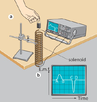
a: Explain why an e.m.f. is induced in the coil as the magnet enters it (section AB of the trace).
b: Explain why no e.m.f. is induced while the magnet is entirely inside the coil (section BC).
c: Explain why section CD shows a negative trace, why the peak e.m.f. is greater over this section, and why CD represents a shorter time interval than AB.
16) You can turn a bicycle dynamo by hand and cause the lamps to light up. Use the idea of Lenz’s law to explain why it is easier to turn the dynamo when the lamps are switched off than when they are on.