Physics A Level
Chapter 26: Electromagnetic induction 26.5 Everyday examples of electromagnetic induction
Physics A Level
Chapter 26: Electromagnetic induction 26.5 Everyday examples of electromagnetic induction
An induced e.m.f. can be generated in a variety of ways, but can be explained in terms of Faraday’s and Lenz’s laws. An e.m.f. will be induced whenever there is a rate of change of magnetic flux linkage for a circuit or device. In this topic, we will examine the physics behind two devices – a generator and a transformer.
Generators
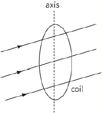
We can generate electricity by spinning a coil in a magnetic field. This is equivalent to using an electric motor backwards. Figure 26.25 shows such a coil in three different orientations as it spins.
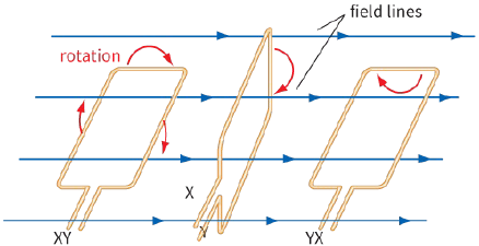
Notice that the rate of change of magnetic flux linkage is maximum when the coil is moving through the horizontal position. In this position, we get a large induced e.m.f. As the coil moves through the vertical position, the rate of change of magnetic flux is zero and the induced e.m.f. is zero.
Figure 26.26 shows how the magnetic flux linkage varies with time for a rotating coil.
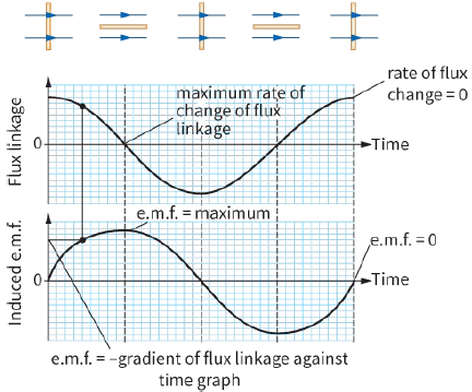
e.m.f. The orientation of the coil is shown above the graphs
According to Faraday’s and Lenz’s laws, the induced e.m.f. is equal to minus the gradient of the flux linkage against time graph:
$E = - \frac{{\Delta (N\Phi )}}{{\Delta t}}$
When the flux linking the coil is:
- maximum, the rate of change of flux linkage is zero and hence the induced e.m.f. is zero
- zero, the rate of change of flux linkage is maximum (the graph is steepest) and hence the induced e.m.f. is also maximum.
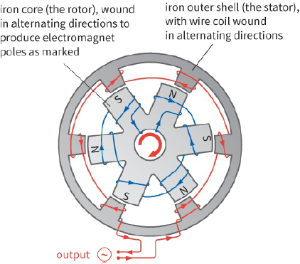
Hence, for a coil like this, we get a varying e.m.f. – this is how alternating current is generated. In practice, it is simpler to keep the large coil fixed and spin an electromagnet inside it (Figure 26.27). A bicycle generator is similar, but in this case a permanent magnet is made to spin inside a fixed coil.
Transformers
You may have studied transformers before your study of this course.
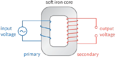
A simple transformer has a primary coil and a secondary coil, both wrapped around a soft iron core (ring).
An alternating current is supplied to the primary coil. This produces a varying magnetic flux in the soft iron core (see Figure 26.28). The secondary coil is linked by the same changing magnetic flux in the soft iron core, so an e.m.f. is induced at the ends of this coil. According to Faraday’s law, you can increase the induced e.m.f. at the secondary coil by increasing the number of turns of the secondary coil. Having fewer turns on the secondary will have the reverse effect.
Transformers are used to transport electrical energy using overhead cables.
Questions
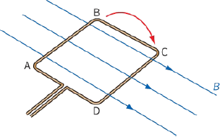
17) Figure 26.29 represents a coil of wire ABCD being rotated in a uniform horizontal magnetic field.
Copy and complete the diagram to show the direction of the current caused by induced e.m.f. in the coil, and the directions of the forces on sides AB and CD that oppose the rotation of the coil.
18) Does a bicycle generator (Figure 26.7) generate alternating or direct current? Justify your answer.
19) The peak e.m.f. induced in a rotating coil in a magnetic field depends on four factors: magnetic flux density B, area of the coil A, number of turns N and frequency f of rotation. Use Faraday’s law to explain why the magnitude of the induced e.m.f. must be proportional to each of these quantities.
20) Explain why, if a transformer is connected to a steady (d.c.) supply, no e.m.f. is induced across the secondary coil.
EXAM-STYLE QUESTIONS
1) Which of the following units is not correct for magnetic flux? [1]
A: $kg\,{m^2}\,{s^{ - 2}}\,{A^{ - 1}}$
B: T
C: $T\,{m^2}$
D: WB
2) A student thinks that electrical current passes through the core in a transformer to the secondary coil. Describe how you might demonstrate that this is not true and explain how an electrical current is actually induced in the secondary coil. Use Faraday’s law in your explanation. [3]
3) A square coil of 100 turns of wire has sides of length $5.0 cm$. It is placed in a magnetic field of flux density $20 mT$, so that the flux is perpendicular to the plane of the coil.
a: Calculate the flux through the coil. [2]
b: The coil is now pulled from the magnetic field in a time of $0.10 s$. Calculate the average e.m.f. induced in it. [3]
[Total: 5]
4) An aircraft of wingspan $40 m$ flies horizontally at a speed of $300 \pm 10\,m\,{s^{ - 1}}$ in a region where the vertical component of the Earth’s magnetic field is $5.0 \times {10^{ - 5}}\,T$.
Calculate the magnitude of the e.m.f. induced between the aircraft’s wingtips; in your answer, include the absolute uncertainty. [5]
5) Figure 28.26 shows the magnetic flux linkage and induced e.m.f. as a coil rotates. Explain why the induced e.m.f. is a maximum when there is no flux linkage and the induced e.m.f. is zero when the flux linkage is a maximum. [4]
6) a: Explain what is meant by a magnetic flux linkage of $1 Wb$. [2]
b: This is a graph of magnetic flux density through a 240 turn coil with a cross-sectional area $1.2 \times {10^{ - 4}}\,{m^2}$ against time.
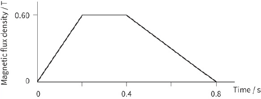
i- Determine the maximum rate of change of flux in the coil. [2]
ii- Determine the maximum magnitude of the induced e.m.f. in the coil. [2]
iii- Sketch a diagram to show the induced e.m.f. varies with time. Mark values on both the e.m.f. and time axes. [2]
[Total: 8]
7) This diagram shows a square coil about to enter a region of uniform magnetic field of magnetic flux density $0.30 T$. The magnetic field is at right angles to the plane of the coil. The coil has 150 turns and each side is $2.0 cm$ in length. The coil moves at a constant speed of $0.50\,m\,{s^{ - 1}}$.
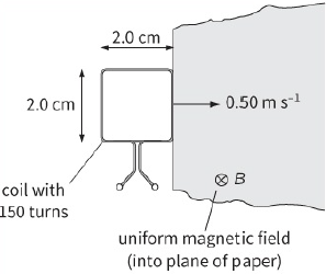
a: i- Calculate the time taken for the coil to completely enter the region of magnetic field. [1]
ii- Determine the magnetic flux linkage through the coil when it is all within the region of magnetic field. [2]
b: Explain why the magnitude of the induced e.m.f. is constant while the coil is entering the magnetic field. [1]
c: Use your answer to part a to determine the induced e.m.f. across the ends of the coil. [4]
d: Explain the induced e.m.f. across the ends of the coil when it is completely within the magnetic field. [2]
e: Sketch a graph to show the variation of the induced e.m.f. with time from the instant that the coil enters the magnetic field. Your time axis should go from 0 to $0.08 s$. [2]
[Total: 12]
8) a: State Faraday’s law of electromagnetic induction. [2]
b: A circular coil of diameter $200 mm$ has 600 turns is shown. It is placed with its plane perpendicular to a horizontal magnetic field of uniform flux density $50 mT$. The coil is then rotated through ${90^ \circ }$ about a vertical axis in a time of $120 ms$.
Calculate:
i- the magnetic flux passing through the coil before the rotation [2]
ii- the change of magnetic flux linkage produced by the rotation [2]
iii- the average magnitude of the induced e.m.f. in the coil during the rotation. [2]
[Total: 8]
9) A bicycle wheel is mounted vertically on a metal axle in a horizontal magnetic field, as shown in the diagram. Sliding connections are made to the metal edge of the wheel and to the metal axle.
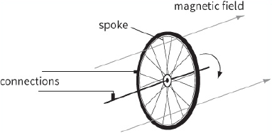
a: i- Explain why an e.m.f. is induced when the wheel rotates. [2]
ii- State and explain two ways in which this e.m.f. can be increased. [2]
b: The wheel rotates five times per second and has a radius of $15 cm$. The magnetic flux density may be assumed to be uniform and of value $5.0 \times {10^{ - 3}}\,T$
Calculate:
i- the area swept out each second by one spoke [2]
ii- the induced e.m.f. between the contacts. [2]
[Total: 8]
SELF-EVALUATION CHECKLIST
After studying the chapter, complete a table like this:
| I can | See topic… | Needs more work | Almost there | Ready to move on |
| define magnetic flux $\Phi $ | 26.2 | |||
|
recall and use: $\Phi = BA$ |
26.2 | |||
| understand and use the concept of magnetic flux linkage | 26.2 | |||
| understand and explain experiments that produce an e.m.f. induced in circuits | 26.2 | |||
| recall and use Faraday’s and Lenz’s laws of electromagnetic induction. | 26.4, 26.5 |