Chapter 27: Alternating currents 27.1 Sinusoidal current
Physics A Level
Chapter 27: Alternating currents 27.1 Sinusoidal current
2022-11-22
118
Crash
report
Physics (9702)
Chapter 1: Kinematics
Chapter 2: Accelerated motion
Chapter 3: Dynamics
Chapter 4: Forces
Chapter 5: Work, energy and power
Chapter 6: Momentum
Chapter 7: Matter and materials
Chapter 8: Electric current
Chapter 9: Kirchhoff’s laws
Chapter 10: Resistance and resistivity
Chapter 11: Practical circuits
Chapter 12: Waves
Chapter 13: Superposition of waves
Chapter 14: Stationary waves
Chapter 15: Atomic structure
P1 Practical skills at AS Level
Chapter 16: Circular motion
Chapter 17: Gravitational fields
Chapter 18: Oscillations
Chapter 19: Thermal physics
Chapter 20: Ideal gases
Chapter 21: Uniform electric fields
Chapter 22: Coulomb’s law
Chapter 23: Capacitance
Chapter 24: Magnetic fields and electromagnetism
Chapter 25: Motion of charged particles
Chapter 26: Electromagnetic induction
Chapter 27: Alternating currents
Chapter 28: Quantum physics
Chapter 29: Nuclear physics
Chapter 30: Medical imaging
Chapter 31: Astronomy and cosmology
P2 Practical skills at A Level
LEARNING INTENTIONS
In this chapter you will learn how to:
- understand and use the terms period, frequency and peak value as applied to an alternating current or voltage
- use equations of the form $x = {x_0}$ sin ωt representing a sinusoidally alternating current or voltage - recall and use the fact that the mean power in a resistive load is half the maximum power for a sinusoidal alternating current
- distinguish between root-mean-square (r.m.s.) and peak values and recall and use ${I_{r.m.s.}} = \frac{{{I_0}}}{{\sqrt 2 }}$ and ${V_{r.m.s.}} = \frac{{{V_0}}}{{\sqrt 2 }}$ for a sinusoidal alternating current
- distinguish graphically between half-wave and full-wave rectification
- explain the use of a single diode for the half-wave rectification of an alternating current
- explain the use of four diodes (bridge rectifier) for the full-wave rectification of an alternating current
- analyse the effect of a single capacitor in smoothing, including the effect of the value of capacitance and the load resistance.
BEFORE YOU START
- In pairs, try to recall and explain the relationship for power dissipation in terms of current, potential difference and resistance from Chapter 8.
- The physics of alternating currents has similarities with simple harmonic motion (see Chapter 18).
Discuss what you remember about period, frequency and angular frequency.
- Write down what you know about the behaviour of diodes in circuits. What’s the most important property of a diode?
- Discuss the discharge of a capacitor through a resistor. Can you remember the factors that affect the time constant of a circuit?
DESCRIBING ALTERNATING CURRENT
In many countries, mains electricity is a supply of alternating current (a.c.). The first mains electricity supplies were developed towards the end of the 19th century; at that time, a great number of different voltages and frequencies were used in different places. In some places, the supply was direct current (d.c.). Nowadays, this has been standardised across much of the world, with standard voltages of $110 V$ or $230 V$ (or similar), and frequencies of $50 Hz$ or $60 Hz$.
Mains electricity is transported along many kilometres of high-voltage power lines (cables).
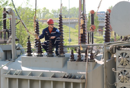
Transformers are used for stepping-up and stepping-down alternating voltages between the power stations and the consumers (Figure 27.1). From your prior knowledge of transformers and transmission of electrical energy, can you remember why it is necessary for power lines to use high voltage?
Figure 27.1: This engineer is working on a transformer used for increasing (stepping-up) the size of the alternating voltage to help with the transportation of electrical energy.
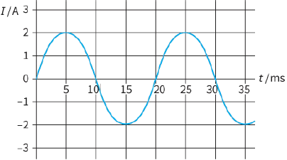
An alternating current can be represented by a graph such as that shown in Figure 27.2. This shows that the current varies regularly. During half of the cycle, the current is positive, and in the other half it is negative. This means that the direction of the current reverses every half cycle. Whenever you use a mains appliance, the charges (free electrons) within the wire and appliance flow backwards and forwards.
At any instant in time, the current has a particular magnitude and direction given by the graph.
The graph has the same shape as the graphs used to represent simple harmonic motion (s.h.m.) (see Chapter 18), and it can be interpreted in the same way. In a wire with a.c., the free electrons within the wire move back and forth with s.h.m. The variation of the current with time is a sine curve, so it is described as sinusoidal. (In principle, any current whose direction changes between positive and negative can be described as alternating, but we will only be concerned with those that have a regular, sinusoidal pattern.)
Figure 27.2: A graph to represent a sinusoidal alternating current
An equation for a.c.
As well as drawing a graph, we can write an equation to represent alternating current. This equation gives us the value of the current I at any time t:
$I = {I_0}\,sin\omega t$
where I is the current at time t, ${I_0}$ is the peak value of the alternating current and ω is the angular frequency of the supply, measured in $rad\,{s^{ - 1}}$ (radians per second). The peak value is the maximum magnitude of the current. It’s very much like the ‘amplitude’ of the alternating current, except the unit is that of current.
This is related to the frequency f in the same way as for s.h.m.:
$\omega = 2\pi f$
and the frequency and period are related by:
$f = \frac{1}{T}$
KEY EQUATION
Alternating current:
$I = {I_0}\,sin\omega t$
Remember that your calculator must be in the radian mode when using this equation.
Questions
1) The following questions relate to the graph in Figure 27.2.
a: State the value of the current I and its direction when time $t = 5 ms$.
b: Determine the time the current next has the same value, but negative.
c: State the time T for one complete cycle (the period of the a.c).
d: Determine the frequency of this alternating current.
2) The following questions relate to the graph in Figure 27.2.
a: Determine the values of ${I_0}$ and $\omega $.
b: Write an equation to represent this alternating current.
3) An alternating current, measured in amperes (A), is represented by the equation: $I = 5.0\,\sin \,(120\pi t)$
a: Determine the values of ${I_0}$, $\omega $, f and T.
b: Sketch a graph to represent the current.