Physics A Level
Chapter 27: Alternating currents 27.4 Rectification
Physics A Level
Chapter 27: Alternating currents 27.4 Rectification
Many electrical appliances work with alternating current. Some, like electrical heaters, will work equally well with d.c. or a.c. However, there are many appliances, such as electronic equipment, which require d.c. For these, the alternating mains voltage must be converted to direct voltage by the process of rectification.
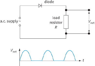
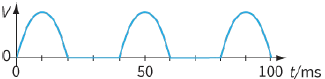
A simple way to do this is to use a diode, which is a component that will only allow current in only one direction. (You have already met diodes in Chapter 10.) Figure 27.11 shows a circuit for doing this. An alternating input voltage is applied to a circuit with a diode and a resistor in series. The diode will only conduct during the positive cycles of the input voltage. Hence, there will be a current in the load resistor only during these positive cycles. The output voltage Vout across the resistor will fluctuate as shown in the Vout against time t graph. This graph is identical to the input alternating voltage, except the negative cycles have been ‘chopped-off’.
This type of rectification is known as half-wave rectification. For one-half of the time the voltage is zero, and this means that the power available from a half-wave rectified supply is reduced.
The bridge rectifier
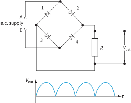
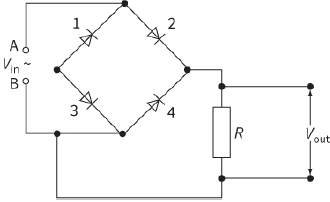
To overcome this problem of reduced power, a bridge rectifier circuit is used. This consists of four diodes
connected across the input alternating voltage, as shown in Figure 27.12. The output voltage Vout is taken across the load resistor R. The resulting output voltage across the load resistor R is full-wave rectified.
The way in which this works is shown in Figure 27.13.
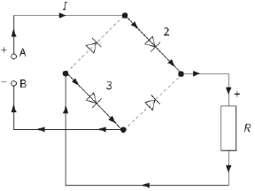
- During the positive cycles of the input voltage, A is positive and B is negative. The diodes 2 and 3 conduct because they are both in forward bias. The diodes 1 and 4 are in reverse bias, and therefore do not conduct. The current in the load resistor R will be downwards. Figure 27.13a shows the direction of the current.
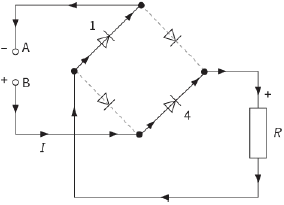
- During the negative cycles of the input voltage, B is positive and A is negative. The diodes 4 and 1 conduct because they are now both in forward bias. The diodes 2 and 3 are in reverse bias, and therefore do not conduct. The current in the load resistor R will still be downwards. Figure 27.13b shows the direction of the current.
|
|
Note that in both positive and negative cycles, the current direction in the load resistor R is always the same (downwards). This means that the top end of R must always be positive.
You can construct a bridge rectifier using light-emitting diodes (LEDs) that light up when current flows through them. By connecting this bridge to a slow a.c. supply (for instance, $1 Hz$ from a signal generator), you can see the sequence in which the diodes conduct during rectification.
Question
Explain why, when terminal B in Figure 27.13 is positive (during the negative cycles), only diodes 1 and 4 conduct.
Smoothing
In order to produce steady d.c. from the ‘bumpy’ d.c. that results from rectification, a smoothing capacitor is necessary in the circuit. This capacitor, of capacitance C, is in parallel with the load resistor of resistance R. This is shown in Figure 27.14. The idea is that the capacitor charges up and maintains the voltage at a high level. It discharges gradually when the rectified voltage drops, but the voltage soon rises again and the capacitor charges up again. The result is an output voltage with ‘ripple’.
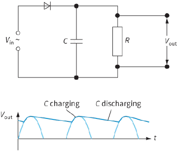
The amount of ripple can be controlled by carefully choosing the capacitance C of the capacitor and the resistance R of the load resistor. A capacitor with a large capacitance value discharges more slowly than a capacitor with a small capacitance value, so will give a smaller ripple. Similarly, if the resistance R of the resistor is increased, then this too leads to a slower discharge of the capacitor. You may have already met the physics of discharging capacitors in Chapter 23. So, the size of the ripple can be reduced by increasing the time constant CR of the capacitor–resistor circuit. Ideally, though this is definitely not a general rule, CR must be much greater than the time interval between the adjacent peaks of the output signal – you want the capacitor to be still discharging between the ‘gaps’ between the positive cycles.
This is illustrated in Worked example 2.
Note that, in Figures 27.11 to 27.14, we have represented the load on the supply by a resistor. This represents any components that are connected to the supply. For example, a rectifier circuit can be used to charge the battery of a mobile phone or provide a direct voltage supply for small radio.
Questions
12) Sketch the following voltage patterns:
a: a sinusoidal alternating voltage
b: the same voltage as part a, but half-wave rectified
c: the same voltage as part b, but smoothed
d: the same voltage as part a, but full-wave rectified
e: the same voltage as part d, but smoothed.
13) A student wires a bridge rectifier incorrectly as shown in Figure 27.16. Explain what you would expect to observe when an oscilloscope is connected across the load resistor R.
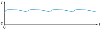
14) A bridge rectifier circuit is used to rectify an alternating current through a resistor. A smoothing capacitor is connected across the resistor. Figure 27.17 shows how the current varies. Use sketches
to show the changes you would expect:
a: if the resistance R of the resistor is increased
b: if the capacitance C of the capacitor is decreased.
EXAM-STYLE QUESTIONS
1) The maximum power dissipated in a resistor carrying an alternating current is $10 W$.
What is the mean power dissipated in the resistor? [1]
A: $5.0 W$
B: $7.1 W$
C: $10 W$
D: $14 W$
2) The alternating current I in ampere (A) in a filament lamp is represented by the equation:
$I = 1.5\,sin\,(40t)$.
Which of the following is correct? [1]
A: The angular frequency of the alternating current is $40\,rad\,{s^{ - 1}}$.
B: The frequency of alternating current is $40 Hz$.
C:The maximum current is $3.0 A$.
The peak voltage is $1.5 V$.
3) Write down a general expression for the sinusoidal variation with time t of:
a: an alternating voltage V [1]
b: an alternating current I (you may assume that I and V are in phase) [1]
c: the power P dissipated due to this current and voltage. [1]
[Total: 3]
4) The alternating current I in ampere (A) in a circuit is represented by the equation:
$I = 2.5\,sin\,(50\pi t)$.
a: State the peak value of the current. [1]
b: Calculate the frequency of the alternating current. [2]
c: Sketch a graph to show two cycles of the variation of current with time.
Mark the axes with suitable values. [2]
d: Calculate Ir.m.s., the r.m.s. value of current, and mark this on your graph in
part c. [1]
e: Determine two values of time t at which the current $I = {I_{r.m.s.}}$. [3]
[Total: 9]
5) A heater of resistance $6.0\,\Omega $ is connected to an alternating current supply. The output voltage from the supply is $20\,{V_{r.m.s.}}$
Calculate:
a: the average power dissipated in the heater [2]
b: the maximum power dissipated in the heater [1]
c: the energy dissipated by the heater in 5.0 minutes. [2]
[Total: 5]
6) An oscilloscope is used to display the variation of voltage across a $200\,\Omega $ resistor with time. The trace is shown. The time-base of the oscilloscope is set
at $2\,ms\,di{v^{ - 1}}$ and the Y-gain at $0.5\,V\,di{v^{ - 1}}$.
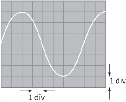
Determine:
a: the period and hence the frequency of the alternating voltage [2]
b: the peak voltage and hence the r.m.s. voltage [2]
c: the r.m.s. current in the resistor [1]
d: the mean power dissipated in the resistor. [2]
[Total: 7]
7) a: State the relationship between the peak current ${I_0}$ and the r.m.s. current ${I_{rms}}$ for a sinusoidally varying current. [1]
b: The current in a resistor connected to a steady d.c. supply is $2.0 A$. When the same resistor is connected to an a.c. supply, the current in it has a peak value of $2.0 A$. The heating effects of the two currents in the resistor are different.
i- Explain why the heating effects are different and state which heating effect is the greater. [2]
ii- Calculate the ratio of the power dissipated in the resistor by the d.c.
current to the power dissipated in the resistor by the a.c. current. [2]
[Total: 5]
8) A sinusoidal voltage of $6.0\,{V_{r.m.s.}}$ and frequency $50 Hz$ is connected to a diode and a resistor R of resistance $400\,\Omega $ as shown in the diagram.
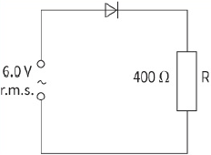
a: Sketch a graph showing the variation with time of both the supply waveform (use a dotted line) and the voltage across R (use a solid line). Put numerical scales on both the voltage and time axes. [4]
b: An uncharged capacitor C is connected across R. When the $6.0\,{V_{r.m.s.}}$
supply is switched on, the capacitor charges fully during the first quarter of a cycle. You may assume that the p.d. across the diode is zero when it conducts. For the next three-quarters of the first cycle, the diode stops conducting and the p.d. across R falls to one-half of the peak value. During this time the mean p.d. across R is $5.7 V$.
For the last three-quarters of the first cycle, calculate:
i- the time taken [1]
ii- the mean current in R [2]
iii- the charge flowing through R
iv- the capacitance of C. [2]
c: Explain why the diode stops conducting during part of each cycle in part b. [2]
[Total: 13]
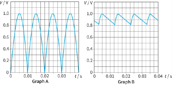
9) The rectified output from a circuit is connected to a resistor R of resistance $1000\,\Omega $. Graph A shows the variation with time t of the p.d. V across the resistor. Graph B shows the variation of V when a capacitor is placed across R to smooth the output.
Explain how the rectification is achieved. Draw a circuit diagram to show the components involved. [6]
b: Explain the action of the capacitor in smoothing the output. [3]
c: Using graph B between $t = 0.005$ and $t = 0.015 s$, determine:
i- the time during which the capacitor is charging [1]
ii- the mean value of the p.d. across R [1]
iii- the average power dissipated in R. [2]
[Total: 13]
10) Electrical energy is supplied by a high-voltage power line that has a total resistance of $4.0\,\Omega $. At the input to the line, the root-mean-square (r.m.s.)
voltage has a value of $400 kV$ and the input power is $500 MW$.
a: i- Explain what is meant by root-mean-square voltage. [2]
ii- Calculate the minimum voltage that the insulators that support the line
must withstand without breakdown. [2]
b: i- Calculate the value of the r.m.s. current in the power line. [2]
ii- Calculate the power loss on the line. [2]
iii- Suggest why it is an advantage to transmit the power at a high voltage. [2]
[Total: 10]
11) A student has designed a full-wave rectifier circuit.
The output voltage for this circuit is taken across a resistor of resistance $120\,\Omega $ . The variation of the output voltage with time is shown.
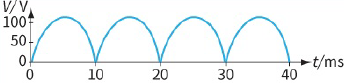
A capacitor is now connected across the resistor. The graph shows the new variation of the output voltage with time.
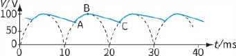
a: Explain the variation of the output variation between points:
i- AB [1]
ii- BC. [1]
b: Use the second graph to determine the value of the capacitance C. [3]
(You may use the equation $V = {V_0}e{\,^{ - \frac{t}{{CR}}}}$ from Chapter 23.)
[Total: 5]
SELF-EVALUATION CHECKLIST
After studying the chapter, complete a table like this:
| I can | See topic… | Needs more work | Almost there | Ready to move on |
| understand the terms period, frequency and peak value as applied to an alternating current or voltage | 26.1, 26.2 | |||
| use the equations $I - {I_0}\,\sin \,\omega t$ and $V = {V_0}\,\sin \,\omega t$ for sinusoidally alternating current and voltage, respectively | 26.1, 26.2 | |||
| understand that the mean power in a resistive load is half the maximum power for a sinusoidal alternating current | 27.3 | |||
| understand root-mean-square (r.m.s.) and peak values | 27.3 | |||
| recall and use: | 27.3 | |||
| understand half-wave and full-wave rectification |
27.4 | |||
| explain how a single diode produces half-wave rectification |
27.4 | |||
| explain how four diodes (bridge rectifier) produce full-wave rectification | 27.4 | |||
| understand smoothing capacitors, and understand how smoothing effects are governed by capacitance of the smoothing capacitor and the resistance of the load resistor. | 27.4 |