Physics A Level | Chapter 10: Resistance and resistivity 10.3 Resistance and temperature
A conductor that does not obey Ohm’s law is described as non-ohmic. An example is a filament lamp.
Figure 10.3 shows such a lamp; you can clearly see the wire filament glowing as the current passes through it. Figure 10.4 shows the I–V characteristic for a similar lamp.
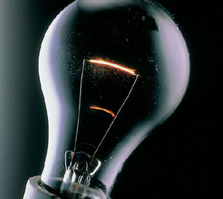
This shows that the lamp produces both heat and light
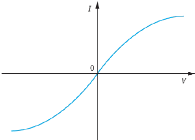
- The line passes through the origin (as for an ohmic component).
- For very small currents and voltages, the graph is roughly a straight line.
- At higher voltages, the line starts to curve. The current is a bit less than we would have expected from a straight line. This suggests that the lamp’s resistance has increased. You can also tell that the resistance has increased because the ratio $\frac{V}{I}$ is larger for higher voltages than for low voltages.
The graph of Figure 10.4 is not a straight line–this shows that the resistance of the lamp depends on the temperature of its filament. Its resistance may increase by a factor as large as ten between when it is cold and when it is brightest (when its temperature may be as high as ${1750^ \circ }C$).
Thermistors
Thermistors are components that are designed to have a resistance that changes rapidly with temperature. Thermistors (‘thermal resistors’) are made from metal oxides such as those of manganese and nickel.
There are two different types of thermistor:
- Negative temperature coefficient (NTC) thermistors – the resistance of this type of thermistor decreases with increasing temperature. Those commonly used for physics teaching may have a resistance of many thousands of ohms at room temperature, falling to a few tens of ohms at ${100^ \circ }C$.
You should become familiar with the properties of NTC thermistors.
- Positive temperature coefficient (PTC) thermistors–the resistance of this type of thermistor rises abruptly at a definite temperature, usually around $100\, - \,{150^ \circ }C$.
In this course, you only need to know about NTC thermistors. So, whenever thermistors are mentioned, assume that it refers to an NTC thermistor.
The change in their resistance with temperature gives thermistors many uses. Examples include:
- water temperature sensors in cars and ice sensors on aircraft wings – if ice builds up on the wings, the thermistor ‘senses’ this temperature drop and a small heater is activated to melt the ice - baby breathing monitors–the baby rests on an air-filled pad, and as he or she breathes, air from the pad passes over a thermistor, keeping it cool; if the baby stops breathing, the air movement stops, the thermistor warms up and an alarm sounds - fire sensors – a rise in temperature activates an alarm - overload protection in electric razor sockets – if the razor overheats, the thermistor’s resistance decreases, the current increases rapidly and cuts off the circuit.
Questions
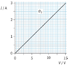
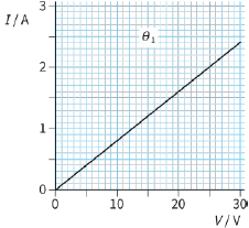
3) The two graphs in Figure 10.5 show the I–V characteristics of a metal wire at two different temperatures, ${\theta _1}$ and ${\theta _2}$.
a: Calculate the resistance of the wire at each temperature.
b: State which is the higher temperature, ${\theta _1}$ or ${\theta _2}$.
|
|
|
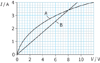
4) The graph in Figure 10.6 shows the I–V characteristics of two electrical components, a filament lamp and a length of steel wire.
a: Identify which curve relates to each component.
b: State the voltage at which both have the same resistance.
c: Determine the resistance at the voltage stated in part b.
Diodes
The semiconductor diode is another example of a non-ohmic conductor. A diode is any component that allows electric current in only one direction. Most diodes are made of semiconductor materials. One type, the light-emitting diode or LED, gives out light when it conducts.
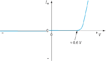
Figure 10.7 shows the I–V characteristic for a diode. There are some points you should notice about this graph.
We have included positive and negative values of current and voltage. This is because, when connected one way round, forward-biased, the diode conducts and has a fairly low resistance.
Connected the other way round, reverse-biased, it allows only a tiny current and has almost infinite resistance.
For positive voltages less than about $0.6 V$, the current is almost zero and hence the diode has almost infinite resistance. It starts to conduct suddenly at its threshold voltage. The resistance of the diode decreases dramatically for voltages greater than $0.6 V$.
straight line. A diode does not obey Ohm’s law
The resistance of a diode depends on the potential difference across it. From this we can conclude that it does not obey Ohm’s law; it is a non-ohmic component.
Diodes are used as rectifiers. They allow current to pass in one direction only and so can be used to convert alternating current into direct current. (There is more about this in Chapter 27.) Most modern diodes are made from silicon and will start conducting when there is a potential difference of about $0.6 V$ across them. You need to remember this key $0.6 V$ value.
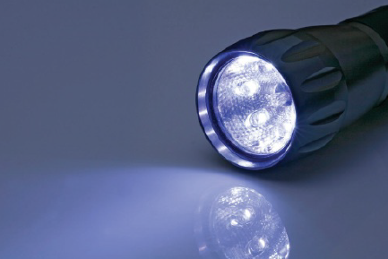
LEDs have traditionally been used as indicator lamps to show when an appliance is switched on. Newer versions, some of which produce white light, are replacing filament lamps, for example, in traffic lights and torches (flashlights) – see Figure 10.8. Although they are more expensive to manufacture, they are more energy-efficient and hence cheaper to run, so that the overall cost is less.
The threshold voltage at which an LED starts to conduct and emit light is higher than $0.6 V$ and depends on the colour of light it emits, but may be taken to be about $2 V$.
lamp
Questions
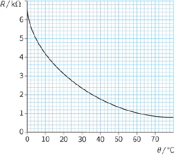
5) The graph in Figure 10.9 was obtained by measuring the resistance R of a particular thermistor as its temperature $\theta $ changed.
a: Determine its resistance at:
i- ${20^ \circ }C$
ii- ${45^ \circ }C$.
b: Determine the temperature when its resistance is:
i- $5000\,\Omega $
ii- $2000\,\Omega $.
6) A student connects a circuit with an NTC thermistor, a filament lamp and a battery in series. The lamp glows dimly. The student warms the thermistor with a hair dryer. What change will the student notice in the brightness of the lamp? Explain your answer.
The light-dependent resistor (LDR)
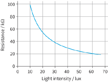
A light-dependent resistor (LDR) is made of a high-resistance semiconductor. If light falling on the LDR is of a high enough frequency, photons are absorbed by the semiconductor. As some photons are absorbed, electrons are released from atoms in the semiconductor. The resulting free electrons conduct electricity and the resistance of the semiconductor is reduced.
The graph in Figure 10.10 shows the variation of the resistance of a typical LDR with light intensity. Only a narrow range of light intensity, measured in lux, is shown. A typical LDR will have a resistance of a few hundred ohms in sunlight, but in the dark its resistance will be millions of ohms.
Understanding the origin of resistance
To understand a little more about the origins of resistance, it is helpful to look at how the resistance of a pure metal wire changes as its temperature is increased. This is shown in the graph in Figure 10.11. You will see that the resistance of the pure metal increases linearly as the temperature increases from ${0^ \circ }\,C$ to ${100^ \circ }\,C$. Compare this with the graph in Figure 10.9 for an NTC thermistor; the thermistor’s resistance decreases very dramatically over a narrow temperature range.
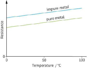
resistance of an impure metal wire is greater than that of a pure metal wire of the same dimensions
Figure 10.11 also shows how the resistance of the metal changes if it is slightly impure. The resistance of an impure metal is greater than that of the pure metal and follows the same gradual upward slope. The resistance of a metal changes in this gradual way over a wide range of temperatures–from close to absolute zero up to its melting point, which may be over ${2000^ \circ }\,C$.
This suggests there are two factors that affect the resistance of a metal:
- the temperature
- the presence of impurities.
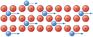
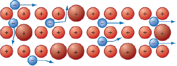
Figure 10.12 shows a simple model that explains what happens in a metal when electrons flow through it.
In a metal, a current is due to the movement of free electrons. At low temperatures, they can move easily past the positive ions (Figure 10.12a). However, as the temperature is raised, the ions vibrate with larger amplitudes. The electrons collide more frequently with the vibrating ions, and this decreases their mean drift velocity. They lose energy to the vibrating ions (Figure 10.12b).
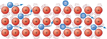
If the metal contains impurities, some of the atoms will be of different sizes (Figure 10.12c). Again, this disrupts the free flow of electrons. In colliding with impurity atoms, the electrons lose energy to the vibrating atoms.
You can see that electrons tend to lose energy when they collide with vibrating ions or impurity atoms.
They give up energy to the metal, so it gets hotter. The resistance of the metal increases with the temperature of the wire because of the decrease in the mean drift velocity of the electrons.
|
|
|
|
Conduction in semiconductors is different. At low temperatures, there are few delocalised, or free, electrons. For conduction to occur, electrons must have sufficient energy to free themselves from the atom they are bound to. As the temperature increases, a few electrons gain enough energy to break free of their atoms to become conduction electrons. The number of conduction electrons thus increases and so the material becomes a better conductor. At the same time, there are more electron–ion collisions, but this effect is small compared with the increase in the number of conduction electrons.
Question
7) The resistance of a metal wire changes with temperature. This means that a wire could be used to sense changes in temperature, in the same way that a thermistor is used.
a: Suggest one advantage a thermistor has over a metal wire for this purpose.
b: Suggest one advantage a metal wire has over a thermistor.