Physics A Level | Chapter 11: Practical circuits 11.2 Potential dividers
How can we get an output of $3.0 V$ from a battery of e.m.f. $6.0 V$? Sometimes we want to use only part of the e.m.f. of a supply. To do this, we use an arrangement of resistors called a potential divider circuit.
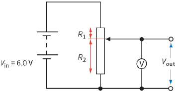
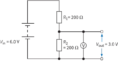
Figure 11.6 shows two potential divider circuits, each connected across a battery of e.m.f. $6.0 V$ and of negligible internal resistance. The high-resistance voltmeter measures the voltage across the resistor of resistance ${R_2}$. We refer to this voltage as the output voltage, Vout, of the circuit. The first circuit, a, consists of two resistors of values ${R_1}$ and ${R_2}$. The voltage across the resistor of resistance ${R_2}$ is half of the $6.0 V$ of the battery. The second potential divider, b, is more useful. It consists of a single variable resistor.
By moving the sliding contact, we can achieve any value of Vout between $0.0 V$ (slider at the bottom) and $6.0 V$ (slider at the top).
|
|
The output voltage Vout depends on the relative values of ${R_1}$ and ${R_2}$. You can calculate the value of ${V_{out}}$ using the potential divider equation:
${V_{out}} = \left( {\frac{{{R_2}}}{{{R_1} + {R_2}}}} \right) \times {V_{in}}$
where ${R_2}$ is the resistance of the component over which the output is taken, ${R_1}$ is the resistance of the second component in the potential divider and Vin is the p.d. across the two components.
Question
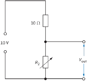
7) Determine the range of ${V_{out}}$ for the circuit in Figure 11.7 as the variable resistor ${R_2}$ is adjusted over its full range from $0\,\Omega $ to $40\,\Omega $. (Assume the supply of e.m.f. $10 V$ has negligible internal resistance.)