Physics A Level | Chapter 13: Superposition of waves 13.4 The Young double-slit experiment
Now we will take a close look at a famous experiment that Thomas Young performed in 1801. He used this experiment to show the wave-nature of light. A beam of light is shone on a pair of parallel slits placed at right angles to the beam. Light diffracts and spreads outwards from each slit into the space beyond.
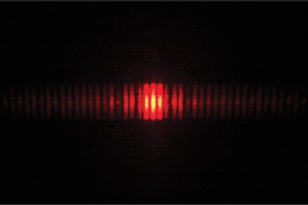
The light from the two slits overlaps on a screen. An interference pattern of light and dark bands called ‘fringes’ is formed on the screen.
Explaining the experiment
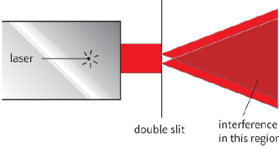
In order to observe interference, we need two sets of waves. The sources of the waves must be coherent–the phase difference between the waves emitted at the sources must remain constant. This also means that the waves must have the same wavelength. Today, this is readily achieved by passing a single beam of laser light through the two slits. A laser produces intense coherent light. As the light passes through the slits, it is diffracted so that it spreads out into the space beyond (Figure 13.20). Now we have two overlapping sets of waves, and the pattern of fringes on the screen shows us the result of their interference (Figure 13.21).
Point A
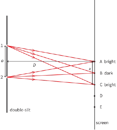
This point is directly opposite the midpoint of the slits. Two rays of light arrive at A, one from slit 1 and the other from slit 2. Point A is equidistant from the two slits, and so the two rays of light have travelled the same distance. The path difference between the two rays of light is zero. If we assume that they were in phase (in step) with each other when they left the slits, then they will be in phase when they arrive at A. Hence they will interfere constructively, and we will observe a bright fringe at A.
Point B
This point is slightly to the side of point A, and is the midpoint of the first dark fringe. Again, two rays of light arrive at B, one from each slit. The light from slit 1 has to travel slightly further than the light from slit 2, and so the two rays are no longer in step. Since point B is at the midpoint of the dark fringe, the two rays must be in antiphase (phase difference of ${180^ \circ }$). The path difference between the two rays of light must be half a wavelength, and so the two rays interfere destructively.
Point C
This point is the midpoint of the next bright fringe, with $AB = BC$. Again, ray 1 has travelled further than ray 2; this time, it has travelled an extra distance equal to a whole wavelength $\lambda $. The path difference between the rays of light is now a whole wavelength. The two rays are in phase at the screen. They interfere constructively, and we see a bright fringe.
The complete interference pattern (Figure 13.21) can be explained in this way.
Question
6) Consider points D and E on the screen in Figure 13.22, where $BC = CD = DE$. State and explain what you would expect to observe at D and E
Determining wavelength $\lambda $
The double-slit experiment can be used to determine the wavelength λ of monochromatic light. The following three quantities have to be measured:
- Slit separation a – This is the distance between the centres of the slits, which is the distance between slits 1 and 2 in Figure 13.22.
- Fringe separation x – This is the distance between the centres of adjacent bright (or dark) fringes, which is the distance AC in Figure 13.22.
- Slit-to-screen distance D – This is the distance from the midpoint of the slits to the central fringe on the screen.
Once these three quantities have been determined, the wavelength $\lambda $ of the light can be found using the relationship:
$\lambda = \frac{{ax}}{D}$
where $\lambda $ is the wavelength of the monochromatic light incident normally at the double-slit. a is the separation between the centres of the slits, x is the separation between the centres of adjacent bright (or dark) fringes and D is distance between the slits and the screen.
Question
7) The student in Worked example 1 moved the screen to a distance of $4.8 m$ from the slits. Determine the fringe separation x now.
PRACTICAL ACTIVITY 13.4
Using Young’s slits to determine $\lambda $
The Young double-slit experiment can be used to determine the wavelength $\lambda $ of monochromatic light.
Here, we look at a number of practical features of the experiment and consider how the percentage uncertainty in the value of $\lambda $ can be reduced.
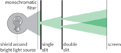
One way to carry out the double-slit experiment is shown in Figure 13.23. Here, a white light source is used, rather than a laser. A monochromatic filter allows only one wavelength of light to pass through. A single slit diffracts the light. This diffracted light arrives in phase at the double slit, which ensures that the two parts of the double slit behave as coherent sources of light. The double slit is placed a centimetre or two beyond the single slit, and the fringes are observed on a screen a metre or so away.
The experiment has to be carried out in a darkened room, as the intensity of the bright fringes is low – making them hard to see.
There are three important factors involved in the way the equipment is set up:
- All slits are a fraction of a millimetre in width. Since the wavelength of light is less than a micrometre ($10−6 m$), this gives a small amount of diffraction in the space beyond. If the slits were narrower, the intensity of the light would be too low for visible fringes to be achieved.
- The double slits are about a millimetre apart. If they were much further apart, the fringes would be too close together to be distinguishable.
- The screen is about a metre from the slits. The fringes produced are clearly separated without being too dim.
Measuring a, x and D
Measuring slit separation a: a travelling microscope is suitable for measuring a. It is difficult to judge the position of the centre of a slit. If the slits are the same width, the separation of their left-hand edges is the same as the separation of their centres.
Measuring fringe width x: it is best to measure across several fringes (say, ten) and then to calculate the average separation later. A $30 cm$ ruler or a travelling microscope can be used.
Measuring the slit-to-screen distance D: this can be measured using a metre rule or a tape measure.
Reducing percentage errors
Why use a laser rather than white light? With a laser, the light beam is more concentrated, and the initial single slit is not necessary. The greater intensity of the beam means that the screen can be further from the slits, so that the fringes are further apart. This reduces the percentage uncertainties in measurements of x and D. Consequently, the overall percentage uncertainty in the calculated value for the wavelength $\lambda $ will be smaller.
A laser has a second advantage. The light from a laser is monochromatic; that is, it consists of a single wavelength. This makes the fringes very clear, and they are present in large numbers across the screen. With white light, a range of wavelengths is present. Different wavelengths form fringes at different points across the screen, smearing them out so that they are not as clear.
Using white light with no filter results in a central fringe that is white (because all wavelengths are in phase here), but the other fringes show coloured effects, as the different wavelengths interfere constructively at different points. In addition, only a few fringes are visible in the interference pattern.
Questions
8) Use the equation to explain the following observations:
a: With the slits closer together, the fringes are further apart.
b: Interference fringes for blue light are closer together than for red light.
c: In an experiment to measure the wavelength of light, it is desirable to have the screen as far from the slits as possible.
9) Yellow light from a sodium source is used in the double-slit experiment. This yellow light has wavelength $589 nm$. The slit separation is $0.20 mm$, and the screen is placed $1.20 m$ from the slits.
Calculate the separation between adjacent bright fringes formed on the screen.
10) In a double-slit experiment, filters were placed in front of a white light source to investigate the effect of changing the wavelength of the light. At first, a red filter was used instead ($\lambda = 600\,nm$) and the fringe separation was found to be $2.4 mm$. A blue filter was then used instead ($\lambda = 450\,nm$).
Calculate the fringe separation with the blue filter.