Physics A Level | Chapter 25: Motion of charged particles 25.2 Orbiting charged particles
Consider a charged particle of mass m and charge Q moving at right angles to a uniform magnetic field. It will describe a circular path because the magnetic force F is always perpendicular to its velocity. The magnetic force F, provides the centripetal force on the particle – the direction of the force is always towards the centre of the circle.
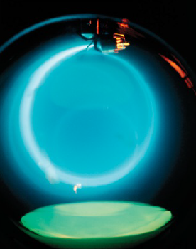
Figure 25.8 shows a fine-beam tube. In this tube, a beam of fast-moving electrons is produced by an electron gun. This is similar to the cathode and anode shown in Figure 25.4, but in this case the beam is directed vertically downwards as it emerges from the gun. It enters the spherical tube, which has a uniform horizontal magnetic field. The beam is at right angles to the magnetic field and the Bev force pushes it round in a circle.
The fact that the centripetal force is provided by the magnetic force BQv, gives us a clue as to how we can calculate the radius r of the orbit of a charged particle in a uniform magnetic field. The centripetal force is given by:
$centripetal\,force = \frac{{m{v^2}}}{r}$
Therefore
$BQv = \frac{{m{v^2}}}{r}$
Cancelling and rearranging, you get:
$r = \frac{{mv}}{{BQ}}$
If the charged particles are electrons, then Q is numerically equal to e. The equation then becomes:
$r = \frac{{mv}}{{Be}}$
The momentum p of the particle is mv. You can therefore write the equation as:
$p = Ber$
The equation $r = \frac{{mv}}{{Be}}$ shows that:
- faster-moving particles move in bigger circles because $r \propto \,v$
- particles with greater masses also move in bigger circles because $r \propto \,m$
- particles with greater charge move in tighter (smaller) circles because $r \propto \frac{1}{Q}$
- a stronger field (greater magnetic flux density) makes the particles move in tighter circles because $r \propto \frac{1}{B}$
These ideas have a variety of scientific applications, such as particle accelerators and mass spectrometers. They can also be used to find the charge-to-mass ratio $\frac{e}{{{m_e}}}$ of an electron.
The charge-to-mass ratio of an lectron
Experiments to find the mass of an electron first involve finding the charge-to-mass ratio $\frac{e}{{{m_e}}}$. This is known as the specific charge on the electron – the word ‘specific’ here means ‘per unit mass’.
Using the equation for an electron travelling in a circle in a magnetic field, we have $\frac{e}{{{m_e}}} = \frac{v}{{Br}}$. Clearly, measurements of v, B and r are needed to determine $\frac{e}{{{m_e}}}$.
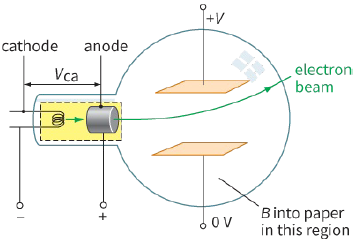
There are difficulties in measuring B and r. For example, it is difficult to directly measure r with a ruler outside the tube in Figure 25.8 because of parallax error. Also, v must be measured, and you need to know how this is done. One way is to use the potential difference (p.d.) ${V_{ca}}$ between the cathode and the anode. This p.d. causes each electron to accelerate as it moves from the cathode to the anode. An individual electron has charge $−e$, therefore an amount of work is done on each electron is $e \times {V_{ca}}$. This is equivalent to the kinetic energy of the electron as it leaves the anode – we assume that the electron has zero kinetic energy at the cathode. Therefore:
$e{V_{ca}} = \frac{1}{2}{m_e}{v^2}$
where ${m_e}$ is the mass of the electron and v is the final speed of the electron.
Eliminating v from the equations:
$e{V_{ca}} = \frac{1}{2}{m_e}{v^2}$ and $r = \frac{{{m_e}v}}{{Be}}$
gives: $\frac{e}{{{m_e}}} = \frac{{2{V_{ca}}}}{{{r^2}{B^2}}}$
A voltmeter can be used to measure ${V_{ca'}}$, and if r and B are known, we can calculate the ratio $\frac{e}{{{m_e}}}$. As you shall see shortly, the charge on the electron e can be measured more directly, and this allows physicists to calculate the electron mass me from the value of $\frac{e}{{{m_e}}}$.
Questions
4) Look at the photograph of the electron beam in the fine-beam tube (Figure 25.8).
State the direction is the magnetic field (into or out of the plane of the photograph).
5) The particles in the circular beam shown in Figure 25.8 all travel round in the same orbit.
State what can you deduce about their mass, charge and speed.
6) An electron beam in a vacuum tube is directed at right angles to a magnetic field, so that it travels along a circular path.
Predict the effect on the size and shape of the path that would be produced (separately) by each of the following changes:
a: increasing the magnetic flux density
b: reversing the direction of the magnetic field
c: slowing down the electrons
d: tilting the beam, so that the electrons have a component of velocity along the magnetic field.
PRACTICAL ACTIVITY 25.2
The deflection tube
A deflection tube (Figure 25.9) is designed to show a beam of electrons passing through a combination of electric and magnetic fields.
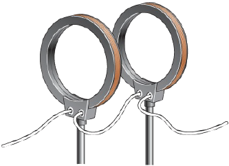
By adjusting the strengths of the electric and magnetic fields, you can balance the two forces on the electrons, and the beam will remain horizontal. The magnetic field is provided by two vertical coils, called Helmholtz coils (Figure 25.10), which give a very uniform field in the space between them.
When the electron beam remains straight, it follows that the electric and magnetic forces on each electron must have the same magnitude and act in opposite directions.
Therefore: electric force (upwards) = magnetic force (downwards)
$eE = Bev$
where E is the electric field strength between the parallel horizontal plates. The speed ν of the electrons is simply related to E and B because e in the expression cancels out. Therefore:
$v = \frac{E}{B}$
The electric field strength E is given by:
$E = \frac{V}{d}$
where V is the p.d. between the plates and d is the distance between the plates. Therefore:
$v = \frac{V}{{Bd}}$