Physics A Level
Chapter 9: Kirchhoff’s laws 9.3 Applying Kirchhoff’s laws
Physics A Level
Chapter 9: Kirchhoff’s laws 9.3 Applying Kirchhoff’s laws
Figure 9.11 shows a more complex circuit, with more than one ‘loop’. Again, there are two batteries and two resistors. The problem is to find the current in each resistor. There are several steps in this; Worked example 2 shows how such a problem is solved.
Signs and directions
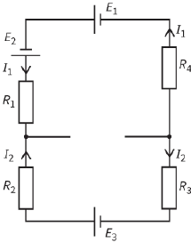
Caution is necessary when applying Kirchhoff’s second law. You need to take account of the ways in which the sources of e.m.f. are connected and the directions of the currents. Figure 9.12 shows one loop from a larger complicated circuit to illustrate this point. Only the components and currents in this particular loop are shown.
e.m.f.s
Starting with the cell of e.m.f. ${E_1}$ and working anticlockwise around the loop (because E1 is ‘pushing current’
anticlockwise):
$sum\,of\,e.m.f.s = {E_1} + {E_2} - {E_3}$
Note that ${E_3}$ is opposing the other two e.m.f.s.
p.d.s
Starting from the same point, and working anticlockwise again:
$sum\,of\,p.d.s = {I_1}{R_1} - {I_2}{R_2} - {I_2}{R_3} + {I_1}{R_4}$
Note that the direction of current ${I_2}$ is clockwise, so the p.d.s that involve ${I_2}$ are negative.
Questions
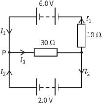
6) You can use Kirchhoff’s second law to find the current I in the circuit shown in Figure 9.13. Choosing the best loop can simplify the problem.
a: Which loop in the circuit should you choose?
b: Calculate the current I.
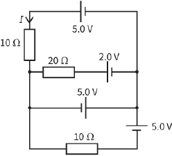
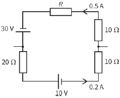
7) Use Kirchhoff’s second law to deduce the resistance R of the resistor shown in the circuit loop of Figure 9.14.
Conservation of energy
Kirchhoff’s second law is a consequence of the principle of conservation of energy. If a charge, say $1 C$, moves around the circuit, it gains energy as it moves through each source of e.m.f. and loses energy as it passes through each p.d. If the charge moves all the way round the circuit so that it ends up where it started, it must have the same energy at the end as at the beginning. (Otherwise we would be able to create energy from nothing simply by moving charges around circuits.)
So:
energy gained passing through sources of e.m.f. = energy lost passing through components with p.d.s
You should recall that an e.m.f. in volts is simply the energy gained per $1 C$ of charge as it passes through a source.
Similarly, a p.d. is the energy lost per $1 C$ as it passes through a component.
1 volt = 1 joule per coulomb
Hence, we can think of Kirchhoff’s second law as:
energy gained per coulomb around loop = energy lost per coulomb around loop
Here is another way to think of the meaning of e.m.f. A $1.5 V$ cell gives $1.5 J$ of energy to each coulomb of charge that passes through it. The charge then moves round the circuit, transferring the energy to components in the circuit. The consequence is that, by driving $1 C$ of charge around the circuit, the cell transfers $1.5 J$ of energy.
Hence, the e.m.f. of a source simply tells us the amount of energy (in joules) transferred by the source in driving unit charge ($1 C$) around a circuit..
Questions
8) Use the idea of the energy gained and lost by a $1 C$ charge to explain why two $6 V$ batteries connected together in series can give an e.m.f. of $12 V$ or $0 V$, but connected in parallel they give an e.m.f. of $6 V$.
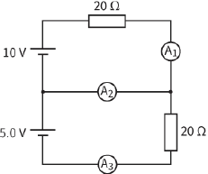
9) Apply Kirchhoff’s laws to the circuit shown in Figure 9.15 to determine the current that will be shown by the ammeters ${A_1}\,,\,{A_2}$ and ${A_3}$.